At the September 2014 XCSSA meeting I brought a box of SPDIF Coax to Toslink converters, analog to digital converters (to generate digital audio signals), and an oscilloscope, all to see how the raw Coax/Toslink signals look in various conversion configurations, including ultimately 3x conversion. Direct SPDIF coax is better than using Toslink conversion, as I expected. But the differences are quite small, and it looks like many levels of conversion would likely be OK in a digital audio system. I have been using 2x conversion (actually, 4 conversion elements) in my latest digital audio system at 96kHz, and even with other long cables, it has worked fine, and has sounded great. Based on what I saw at the meeting, that is not surprising, though I also demonstrated that a new method of hooking up converters will likely work better than what I have been doing in the past--but I did not have enough equipment to test that directly. I'll discuss what I mean by conversion and how it should be counted as I go along. I also showed that a bandwidth measurement for digital audio transmission should likely go to 20-100 mHz. The 2mHz oscillator I brought was simply too low frequency to give any digital audio transmission systems a meaningful test. The actual 96kHz digital audio signal seemed to use pulses equivalent to a 6mHz square wave, from our Oscilloscope estimation (which I haven't verified). But the risetimes suggested transmission bandwidths in the 35-100mHz range, even with multiple levels of optical conversion.
First off, I connected a Analog to Digital converter to a generic brand 12 foot video cable, and connected that to the 100 Mhz oscilloscope having a special 75 ohm terminator. (I am so lucky to have one of those!) The square pulses of the digital signal are almost perfectly clear and square.

I replaced the 12 foot generic cable with a 6 foot Monster Cable Video 3 75 ohm cable. This specific model was recommended in a Widescreen Review technical test as having good performance. (The Monster Video 2 was only so-so.) It seems to use a solid center conductor, and uses slotted center pin metal plug. It had performance essentially indistinguishable from the 12 foot generic cable.

After doing that test, I cleaned up the picture slightly by reducing intensity and adjusting focus. If I were trying to fool you, I'd delete the second picture and just say this is what the Video 3 cable response looked like. And that's true. But it wouldn't be honestly explaining what caused the difference.
Now the picture is so clean we're seeing high frequency ringing which may be occurring in the SPDIF generating circuitry.
As shown, I think that coax cables 12 feet or less in length actually make very little difference to SPDIF connections. So I won't be paying attention to which coax cables I'm using in these tests, and in any case they were all Belden 75 ohm video cables of one kind or another, terminated with Canare 75 ohm RCA connectors, in lengths of 1 foot to 7 feet. I also didn't pay any attention to the optical cables I was using since they were all short, 6 feet or less. Long Toslink cables might have some ill effects, but I did not bring any long Toslink cables with me. I have used 30 foot Toslink cables with good results, but 30 feet might be getting to the point where some degradation of the signal sets in. But I won't know that from these tests. What I believe makes the most difference are the Coax to Optical and Optical to Coax conversions. And possibly if you used really bad cables or connections, which I didn't do.
But the third scope picture only looks so much cleaner because of scope adjustments. BTW, adjustments in future pictures will vary, because I need to readjust intensity a lot when going to very high speed pictures like the one below. Notice above that the rise time appears to be about one tick mark in a grid having 5 tick marks per 0.05 uS. So one tick mark would be about 0.01uS rise time. Bandwidth is calculated as 0.35/rt. Funny that linked page does exactly the calculation I need, and the result is bandwidth of 35mHz. Much of the bandwidth limitation is likely in the Analog to Digital converter, which doesn't need a 10Ghz buffer to drive SPDIF at 6mHz. Some is also in the scope and cable. The scope is only a 100 mHz scope and likely sufficiently out of calibration to be somewhat less than that. To verify the 0.01uS rise time I pressed the 10x horizontal button.

Well, actually it's better than 0.01uS. Each major division here is 0.005uS, and it seems that the rise time is about that. So now it looks like 70mHz bandwidth. We're possibly getting close to the limits of the scope here, so the actual coax bandwidth might be still higher. Notice that the top squiggles seem to cycle in about 0.01uS, which mean they represent a frequency of 100mHz.
Now I do one set of optical conversion with two conversion elements. I take coax from the ADC and run it through a M-Audio CO2 converter to convert the coax to Toslink. I run a 1 meter Toslink cable to a second M-Audio CO2 to confer to Toslink back to coax, and then to the scope.


You have to look carefully to see any differences in the scope picture. But the 100mHz squiggles down the whole top of the pulse are gone and there's a bit of rounding at the leading edge of the signal pulses. Zooming in, we can see the rise time is now about 0.009uS, so the bandwidth has fallen from 70mHz to 39mHz. One would doubt this would be a problem for any digital audio transmission at 96kHz. (Heck, even very ugly looking digital signals work, and this looks nearly pristine.)

Next I added a second set of optical conversion, by inserting an active optical splitter in between the optical sender in one CO2 and the optical receiver in another CO2. I've had good luck with this active optical splitter, an Inday TLDA1. Don't bother with passive Toslink splitters, they usually don't work.

After inserting the splitter this I had to readjust stability controls in the scope, and the resulting stable pulse is a different one than before, one surrounded by blank pulses and seems narrower--ignore that difference. I also might have changed the time base a bit to get stability. Otherwise, t looks about the same, though you can see some roughness in the top and bottom curves of the pulse, which looks like some kind of added vhf ringing.

As much as I've always thought the Inday Toslink splitter was a surplative product, here it appears like it adds some artifacts compared to using a pair of CO2 converters. Though by necessity I can only test the Inday in combination with a pair of CO2's, so I can't really isolate their effects. But still, I now believe CO2 is better because of cleaner signal and lack of stability issues on the scope. (BTW, the M-Audio CO2 is no longer being made. Isn't that the way things go.)
I tested a different model Inday Toslink splitter, TLDA22, one which gives two optical and one coax output from a single Toslink, a feature I thought was cool, but I had many problems with this unit (and for that reason I have gone to great lengths to duplicate the functionality of the TLDA22 using multiple CO2 devices). Running just as the previous Inday splitter, using Toslink input and Toslink output, and forcing the Toslink cables in upside down as they are too loose the correct way, I got an essentially identical trace from the 96kHz digital. I had previously believed this TLDA22 to have broken 96khz capability, but here it seems to work as well as needed, except perhaps for having similar stability issues as the TLDA1 on the scope.

Now I couldn't run all three CO2's I had brought at the same time because I was missing the 9v DC adapter for it (did I not read the eBay ad carefully?). We couldn't find a suitable 9v DC adapter in the large box of AC adapters at 10bitWorks because the few we found didn't have room for the large center pin in the connector. 9V DC adapters are relatively rare, actually.
But what I could do was use a different SPDIF generator that has both SPDIF and Toslink outputs. That was an Emu 0404 USB, running in standalone mode. Selecting the analog inputs and connecting to the Coax output, it produces pulses with a slightly curved top, suggesting some HF damped resonance around 10mHz, but still a clean looking wave (and it was very stable, note this was a lower sampling rate, probably 44.1kHz, since I can't vary that on an 0404 in standalone mode).


Now I remembered to test one of the CO2's in coax-to-coax mode. The CO2 has a selector switch which can select Bidirectional (the usual choice), Coax-to-Toslink, and Toslink-to-Coax. In Coax-to-Toslink mode the Coax input is converted to Toslink, and, simultaneously, the Coax output operates as a coax pass-through (it's an active splitter, actually). Inserting the a single Coax-to-Coax into the 0404 output chain only made the pulse look better--with a flat top. The rise time (and even ringing, in a later test) appeared identical. Thus the Coax-to-Coax looks better and cleaner than any kind of optical conversion (but I should have chosen the better test signal, arrg!, because on this uglier test signal you can't tell as much):


Next I did something almost opposite. Starting with the Toslink output of the 0404, I ran that to a CO2 in Toslink-to-Coax mode. But I connected from the Toslink output of that CO2 (remember both Toslink and Coax outputs are active in Toslink-to-Coax mode) to another CO2. The second CO2 simply converted Toslink back to coax for the scope. Now this chain actually involves 2 layers of conversion or more precisely 4 conversion elements and one buffer.
Layer 1:
internal signal to Toslink output inside 0404
Toslink to internal signal inside CO2 #1
Layer 2:
internal signal inside CO2 #1 to Toslink output
Toslink to internal signal inside CO2 #2
Buffer
internal signal inside CO2 #2 to Coax output


About the same, though it does look like the rise time has fallen about as much as it did in the first test using 4 optical conversion elements, though the digital audio generators are different and the tests are not exactly comparable. Still, it looks perfectly fine.
By this time I was getting confused and decided to do three tests in a row. Starting with direct from coax from the 0404 to the scope, then taking the optical output of the 0404 through a single CO2 to coax (one layer of conversion, including one element inside the 0404 itself), then the two layers of conversion (same as previous experiment above). You can see some progressive deterioration but not much. The CO2 converters are so clean I don't believe I messed with the scope stability controls at all during these three presentations, though perhaps a tad on the last one.


I tested running the Toslink output of the 0404 into the Inday TLDA1 splitter, then through a CO2 for conversion back to coax. This is two layers of optical conversion again, same as in the last picture above, but with one of the layers occurring within the Inday TLDA1. The result looks to have slightly higher rise time, perhaps, but slightly less clean than the double conversion plus buffer above using two CO2's.


Now for the most conversion I was able to do. Triple layers with one buffer:
Layer 1:
internal signal in 0404 to Toslink output
Toslink to internal signal in Inday TDA1
Layer 2:
internal signal in Inday TDA1 to Toslink output
Toslink to internal signal in CO2 #1
Layer 3
internal signal in CO2 #1 to Toslink output
Toslink to internal signal in CO2 #2
Buffer
internal signal in CO2 #2 to coax output

Despite all the conversion, it still looks pristine, bandwidth at least 35mHz, etc. The Inday splitter adds a tiny bit of ringing, hardly noticeable, but also seems to make the rise time even quicker than without it.
Using the other Inday splitter with coax output, it was hard to get good triggering with 2 layers of conversion. It occurs to me that scope triggering is much like the triggering inside a digital receiver in that it focuses on the transition from very small negative voltage to very small positive voltage. It doesn't look at the scope trace like we do. What I could see beyond the lousy triggering was that the rise time seemed just fine, perhaps even better than the CO2's. But the freedom from ringing makes me prefer the CO2 devices to the Inday devices.
My ultimate hookup for Mac to Living Room Stereo will use two CO2's. The optical output from Mac computer will get converted to coax and optical (Optical->Coax) by CO2 #1. The coax output of CO2#1 will connect to the second CO2, in Coax->Optical mode. Then I will have two optical outputs, one from CO2 #1 and the other from CO2 #2, and one free Coax output, from CO2 #2. The optical outputs go to devices in the kitchen and the Coax output goes through installed wiring to living room.

I had been concerned that the second Toslink outputs would see three layers of conversion, but now I see that is not true. The Toslink output from CO2 #2 sees these 2 layers of optical conversion, plus some coax buffering (which I have determined to have little ill effect):
Conversion Layer 1
Mac internal signal to Toslink output
CO2 #1 Toslink input to internal signal
Buffering Layer 1
internal signal to Coax output
Coax input for CO2 #2 to internal signal
Conversion Layer 2
internal signal to CO2 #2 Toslink output
Toslink to internal signal in receiving device
So this is only two layers of CO2 conversion, which I tested in many ways above. It is not as bad as three layers of optical conversion, which also looked good in testing.
Late on Saturday night I hooked up the two CO2 converters as described above, but the second optical output is not currently connected to anything yet because I will use it to install a Schiit Modi DAC. The other outputs are working perfectly and sounding great, especially the living room connection which now sees only one layer of optical conversion while previously it saw two.
First off, I connected a Analog to Digital converter to a generic brand 12 foot video cable, and connected that to the 100 Mhz oscilloscope having a special 75 ohm terminator. (I am so lucky to have one of those!) The square pulses of the digital signal are almost perfectly clear and square.
I replaced the 12 foot generic cable with a 6 foot Monster Cable Video 3 75 ohm cable. This specific model was recommended in a Widescreen Review technical test as having good performance. (The Monster Video 2 was only so-so.) It seems to use a solid center conductor, and uses slotted center pin metal plug. It had performance essentially indistinguishable from the 12 foot generic cable.
After doing that test, I cleaned up the picture slightly by reducing intensity and adjusting focus. If I were trying to fool you, I'd delete the second picture and just say this is what the Video 3 cable response looked like. And that's true. But it wouldn't be honestly explaining what caused the difference.
Now the picture is so clean we're seeing high frequency ringing which may be occurring in the SPDIF generating circuitry.
As shown, I think that coax cables 12 feet or less in length actually make very little difference to SPDIF connections. So I won't be paying attention to which coax cables I'm using in these tests, and in any case they were all Belden 75 ohm video cables of one kind or another, terminated with Canare 75 ohm RCA connectors, in lengths of 1 foot to 7 feet. I also didn't pay any attention to the optical cables I was using since they were all short, 6 feet or less. Long Toslink cables might have some ill effects, but I did not bring any long Toslink cables with me. I have used 30 foot Toslink cables with good results, but 30 feet might be getting to the point where some degradation of the signal sets in. But I won't know that from these tests. What I believe makes the most difference are the Coax to Optical and Optical to Coax conversions. And possibly if you used really bad cables or connections, which I didn't do.
But the third scope picture only looks so much cleaner because of scope adjustments. BTW, adjustments in future pictures will vary, because I need to readjust intensity a lot when going to very high speed pictures like the one below. Notice above that the rise time appears to be about one tick mark in a grid having 5 tick marks per 0.05 uS. So one tick mark would be about 0.01uS rise time. Bandwidth is calculated as 0.35/rt. Funny that linked page does exactly the calculation I need, and the result is bandwidth of 35mHz. Much of the bandwidth limitation is likely in the Analog to Digital converter, which doesn't need a 10Ghz buffer to drive SPDIF at 6mHz. Some is also in the scope and cable. The scope is only a 100 mHz scope and likely sufficiently out of calibration to be somewhat less than that. To verify the 0.01uS rise time I pressed the 10x horizontal button.
Well, actually it's better than 0.01uS. Each major division here is 0.005uS, and it seems that the rise time is about that. So now it looks like 70mHz bandwidth. We're possibly getting close to the limits of the scope here, so the actual coax bandwidth might be still higher. Notice that the top squiggles seem to cycle in about 0.01uS, which mean they represent a frequency of 100mHz.
Now I do one set of optical conversion with two conversion elements. I take coax from the ADC and run it through a M-Audio CO2 converter to convert the coax to Toslink. I run a 1 meter Toslink cable to a second M-Audio CO2 to confer to Toslink back to coax, and then to the scope.
You have to look carefully to see any differences in the scope picture. But the 100mHz squiggles down the whole top of the pulse are gone and there's a bit of rounding at the leading edge of the signal pulses. Zooming in, we can see the rise time is now about 0.009uS, so the bandwidth has fallen from 70mHz to 39mHz. One would doubt this would be a problem for any digital audio transmission at 96kHz. (Heck, even very ugly looking digital signals work, and this looks nearly pristine.)
Next I added a second set of optical conversion, by inserting an active optical splitter in between the optical sender in one CO2 and the optical receiver in another CO2. I've had good luck with this active optical splitter, an Inday TLDA1. Don't bother with passive Toslink splitters, they usually don't work.
After inserting the splitter this I had to readjust stability controls in the scope, and the resulting stable pulse is a different one than before, one surrounded by blank pulses and seems narrower--ignore that difference. I also might have changed the time base a bit to get stability. Otherwise, t looks about the same, though you can see some roughness in the top and bottom curves of the pulse, which looks like some kind of added vhf ringing.
As much as I've always thought the Inday Toslink splitter was a surplative product, here it appears like it adds some artifacts compared to using a pair of CO2 converters. Though by necessity I can only test the Inday in combination with a pair of CO2's, so I can't really isolate their effects. But still, I now believe CO2 is better because of cleaner signal and lack of stability issues on the scope. (BTW, the M-Audio CO2 is no longer being made. Isn't that the way things go.)
I tested a different model Inday Toslink splitter, TLDA22, one which gives two optical and one coax output from a single Toslink, a feature I thought was cool, but I had many problems with this unit (and for that reason I have gone to great lengths to duplicate the functionality of the TLDA22 using multiple CO2 devices). Running just as the previous Inday splitter, using Toslink input and Toslink output, and forcing the Toslink cables in upside down as they are too loose the correct way, I got an essentially identical trace from the 96kHz digital. I had previously believed this TLDA22 to have broken 96khz capability, but here it seems to work as well as needed, except perhaps for having similar stability issues as the TLDA1 on the scope.
Now I couldn't run all three CO2's I had brought at the same time because I was missing the 9v DC adapter for it (did I not read the eBay ad carefully?). We couldn't find a suitable 9v DC adapter in the large box of AC adapters at 10bitWorks because the few we found didn't have room for the large center pin in the connector. 9V DC adapters are relatively rare, actually.
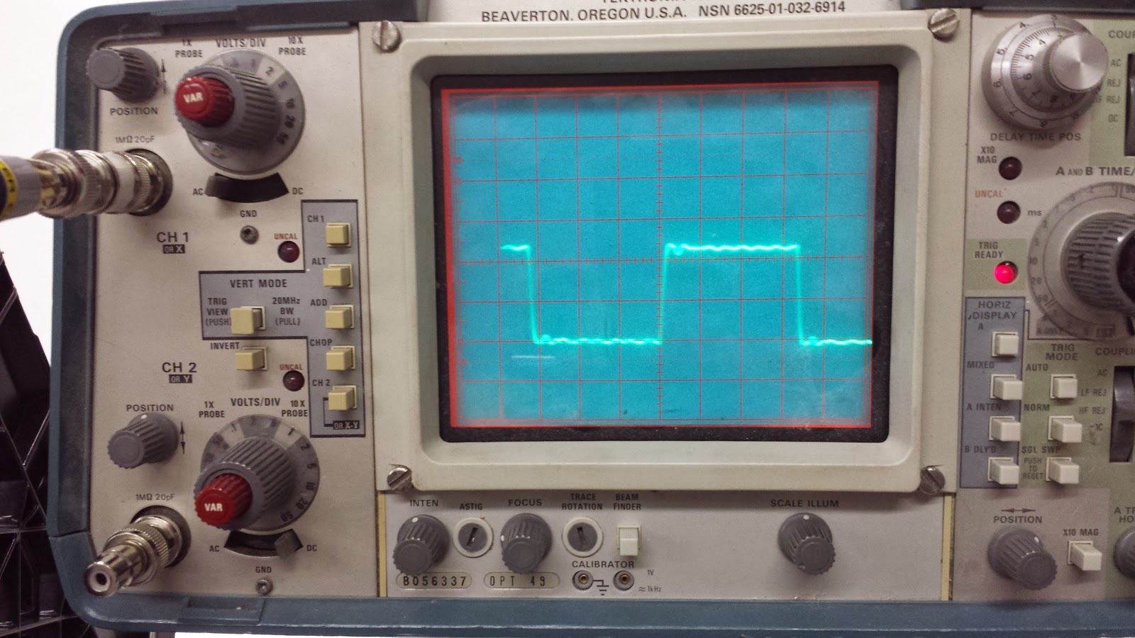
But what I could do was use a different SPDIF generator that has both SPDIF and Toslink outputs. That was an Emu 0404 USB, running in standalone mode. Selecting the analog inputs and connecting to the Coax output, it produces pulses with a slightly curved top, suggesting some HF damped resonance around 10mHz, but still a clean looking wave (and it was very stable, note this was a lower sampling rate, probably 44.1kHz, since I can't vary that on an 0404 in standalone mode).
Now I remembered to test one of the CO2's in coax-to-coax mode. The CO2 has a selector switch which can select Bidirectional (the usual choice), Coax-to-Toslink, and Toslink-to-Coax. In Coax-to-Toslink mode the Coax input is converted to Toslink, and, simultaneously, the Coax output operates as a coax pass-through (it's an active splitter, actually). Inserting the a single Coax-to-Coax into the 0404 output chain only made the pulse look better--with a flat top. The rise time (and even ringing, in a later test) appeared identical. Thus the Coax-to-Coax looks better and cleaner than any kind of optical conversion (but I should have chosen the better test signal, arrg!, because on this uglier test signal you can't tell as much):
Next I did something almost opposite. Starting with the Toslink output of the 0404, I ran that to a CO2 in Toslink-to-Coax mode. But I connected from the Toslink output of that CO2 (remember both Toslink and Coax outputs are active in Toslink-to-Coax mode) to another CO2. The second CO2 simply converted Toslink back to coax for the scope. Now this chain actually involves 2 layers of conversion or more precisely 4 conversion elements and one buffer.
Layer 1:
internal signal to Toslink output inside 0404
Toslink to internal signal inside CO2 #1
Layer 2:
internal signal inside CO2 #1 to Toslink output
Toslink to internal signal inside CO2 #2
Buffer
internal signal inside CO2 #2 to Coax output
About the same, though it does look like the rise time has fallen about as much as it did in the first test using 4 optical conversion elements, though the digital audio generators are different and the tests are not exactly comparable. Still, it looks perfectly fine.
By this time I was getting confused and decided to do three tests in a row. Starting with direct from coax from the 0404 to the scope, then taking the optical output of the 0404 through a single CO2 to coax (one layer of conversion, including one element inside the 0404 itself), then the two layers of conversion (same as previous experiment above). You can see some progressive deterioration but not much. The CO2 converters are so clean I don't believe I messed with the scope stability controls at all during these three presentations, though perhaps a tad on the last one.
I tested running the Toslink output of the 0404 into the Inday TLDA1 splitter, then through a CO2 for conversion back to coax. This is two layers of optical conversion again, same as in the last picture above, but with one of the layers occurring within the Inday TLDA1. The result looks to have slightly higher rise time, perhaps, but slightly less clean than the double conversion plus buffer above using two CO2's.
Now for the most conversion I was able to do. Triple layers with one buffer:
Layer 1:
internal signal in 0404 to Toslink output
Toslink to internal signal in Inday TDA1
Layer 2:
internal signal in Inday TDA1 to Toslink output
Toslink to internal signal in CO2 #1
Layer 3
internal signal in CO2 #1 to Toslink output
Toslink to internal signal in CO2 #2
Buffer
internal signal in CO2 #2 to coax output
Despite all the conversion, it still looks pristine, bandwidth at least 35mHz, etc. The Inday splitter adds a tiny bit of ringing, hardly noticeable, but also seems to make the rise time even quicker than without it.
Using the other Inday splitter with coax output, it was hard to get good triggering with 2 layers of conversion. It occurs to me that scope triggering is much like the triggering inside a digital receiver in that it focuses on the transition from very small negative voltage to very small positive voltage. It doesn't look at the scope trace like we do. What I could see beyond the lousy triggering was that the rise time seemed just fine, perhaps even better than the CO2's. But the freedom from ringing makes me prefer the CO2 devices to the Inday devices.
My ultimate hookup for Mac to Living Room Stereo will use two CO2's. The optical output from Mac computer will get converted to coax and optical (Optical->Coax) by CO2 #1. The coax output of CO2#1 will connect to the second CO2, in Coax->Optical mode. Then I will have two optical outputs, one from CO2 #1 and the other from CO2 #2, and one free Coax output, from CO2 #2. The optical outputs go to devices in the kitchen and the Coax output goes through installed wiring to living room.
I had been concerned that the second Toslink outputs would see three layers of conversion, but now I see that is not true. The Toslink output from CO2 #2 sees these 2 layers of optical conversion, plus some coax buffering (which I have determined to have little ill effect):
Conversion Layer 1
Mac internal signal to Toslink output
CO2 #1 Toslink input to internal signal
Buffering Layer 1
internal signal to Coax output
Coax input for CO2 #2 to internal signal
Conversion Layer 2
internal signal to CO2 #2 Toslink output
Toslink to internal signal in receiving device
So this is only two layers of CO2 conversion, which I tested in many ways above. It is not as bad as three layers of optical conversion, which also looked good in testing.
Late on Saturday night I hooked up the two CO2 converters as described above, but the second optical output is not currently connected to anything yet because I will use it to install a Schiit Modi DAC. The other outputs are working perfectly and sounding great, especially the living room connection which now sees only one layer of optical conversion while previously it saw two.
No comments:
Post a Comment