Saturday, February 5, 2011
The perfect Tact impulse
Well, there it is, I connected one channel Tact output to it's very own input through a Harrison Labs 3dB attenuator. Inside the attenuator is a 2k or thereabouts resistor, which actually causes more like 60dB attenuation into the microphone input load. (Perhaps that explains why previous numbers were in something like the -60dB range.)
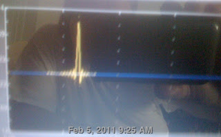
Notice that the pulse is positive only. And notice that the pulse has leading and trailing ringing caused by digital processing. If the speaker had perfect response, it would have identical leading and trailing ringing in it's Tact measurement also.
The leading edge ring relative amplitude looks like about 5% and the trailing edge about 10%. That is considerable. If the speaker lacks those (as, say, the Acoustat by itself might) that actually means it rolling off the highs. If the supertweeter adds them back in, it is not adding ringing so much as restoring the ringing "in the signal" (though it's really in both the signal and the measurement thereof through limited digital means).
It's possible the ringing is at precisely the kinds of high frequencies the supertweeter is supposed to be adding too. Actually, I can test that precisely, by measuring the supertweeter line signal...
Highpass super as high as possible?
I've made lots of interesting tweeter measurements. I can get incredibly steep cutoff simply by moving the crossover cutoff to 20kHz. Loss of volume at the acoustic crossover point is minimal, actually just a 2-3dB. So just boost the level even more. This suggests a rule for supertweeters, at least mine. Highpass supertweeter as high as possible then adjust amplitude up to compensate. The high efficiency "universal" supertweeter seems to be designed like this anyway, though simply for universality, not to optimize cutoff steepness.
The apparent increased highpass steepness at 20kHz crossover could be some combination of tweeter passband inaccuracy, room response, reflections, and, the thing I was obsessing over recently, the supertweeter's own crossover. It makes sense that to make the Behringer highpass interact as little as possible with the Elac's built-in crossover by moving the Behringer as high as possible. However, what one wants is correct operation, not necessarily minimal interaction. But somehow the minimal interaction seems to work out give desired or at least desirable results, which can simply be compensating by raising the level. (Or lowering the level of the other drivers.)
Oh, yes, and it could also be measurement error. I haven't been showing the impulse response, because it looks terrible. My purist friends should be shouting "told you so". The Acoustats by themselves have a very nice impulse. The supertweeter, right now, is simply messing that up badly. Which then brought to my rationalizing mind the question, what does the perfect Tact response look like?
Friday, February 4, 2011
Fun Fun Fun with Tact Measurements
All the last times I've done Tact Room Correction System (RCS) 2.0 corrections on my living room system, I've been in too much of a hurry to really do it right. That's not saying much, I'm sure that will be true this time too.
I'm torn between wanting to get it done badly, and wanting to really dig deep into understanding how I can make my system sound better, using the wealth of potential diagnostic information the Tact can show it it's measurements.
Look only at the steeply rising curve on the right; ignore the room noise from dishwasher etc on the left (low frequencies).
That's my supertweeter, with the full +15dB level and a 15.5kHz crossover. But it looks nothing like the idealized picture that I had in mind (though it's not too far from my Genrad measurement) of a supertweeter with flat response 10-35kHz crossed over at 15.5kHz. Instead, it looks like a highpass filter around 18kHz or so, starts out pretty steep, then gets shallow after awhile, then steep again. You probably can't read the scale, but the range is 50dB and the tweeter is showing 45dB attenuation from the quasi peak at 18kHz and 3kHz. Unfortunately, the Tact isn't showing frequency response above 20kHz. My measurements show a flat range from 16Khz (just above crossover) to 24kHz; none of my microphones are calibrated now and none were calibrated above 20kHz, so I really can't be sure of anything above 20kHz and I have no reason to doubt Elac's 35kHz spec, though perhaps that's a 3dB downpoint.
Anyway, even if we assume more-or-less flatness above 18kHz, why is there so much attenuation between there an the crossover point of 15.5kHz? Funny you should ask, because a Linkwitz-Riley crossover attenuates each driver 6dB at the crossover point. What is the attenuation shown above at 15.5kHz? Let's look at the raw numbers from the Tact (which are not easy to understand at first glance).
18.290kHz -57.34
15.493 -59.97
That's only about 2.7dB attenuation, not the 6dB ideal. So the suspicious looking drop from 18kHz isn't even sufficient? Without checking the theoretic curve, I can't be sure, because even 20kHz isn't sufficiently above the 6dB attenuation point at 15.5kHz to be "flat", the crossover is already attenuating a bit at 20Khz, so I would need to know what the theory would say the response should be at 20kHz (or 18.29kHz).
Anyway, I think it's about right, actually, though it might still be a tad too much attenuation at 15.493 (the closest the Tact lets me measure to 15.5kHz).
Now where do I measure -6dB? The closes point I can find to -6dB from the maximum level of -57.34dB is at 13.811 kHz. This seems to fit with my intent to cross over at that point, but I'm not sure is correct.
Also, the microphone may not be very accurate at these frequencies, and perhaps I erred by aiming it directly at the speaker, and perhaps I am not using the correct Tact, and perhaps (many people
believe this) the Tact microphone calibrations are not very accurate, one might even be better off using a generic calibration with fewer tiny irregularities (some do this).
So there's lots of wiggle room here. Perhaps this is indeed showing the intended LR crossover applied to a roughly flat supertweeter response. Or perhaps, for some reason, this setting is providing the "acoustic" crossover that is more like 14khz, which is after all what I intended to do.
OK, that's one aspect of this, how accurate is the top above the crossover. The answer is, it appears to be not too far off, actual acoustic crossover somewhere between 14kHz and 15.5kHz.
But the other aspect is below the crossover. Is it really crossing over at 48dB per octave. We would expect to see about 48dB attuation around one octave lower. (I don't think you actually achieve 48dB plus 6dB initial attenuation, because during the first octave the attenuation is just ramping up, or down, so to speak.)
At 10.6kHz, about half an octave below the nominal crossover point of 15.5kHz, the response is attenuated by 18.3dB. That doesn't sound adequate (though it is clear I really need a nominal Linkwitz-Riley crossver calculator) because I would think the attenuation should be more like 24dB. And clearly the supertweeter is not much getting out of the way of the Acoustat peak around 14khz, though it is attenuated roughly 6dB there.
I'm torn between wanting to get it done badly, and wanting to really dig deep into understanding how I can make my system sound better, using the wealth of potential diagnostic information the Tact can show it it's measurements.
Look only at the steeply rising curve on the right; ignore the room noise from dishwasher etc on the left (low frequencies).
That's my supertweeter, with the full +15dB level and a 15.5kHz crossover. But it looks nothing like the idealized picture that I had in mind (though it's not too far from my Genrad measurement) of a supertweeter with flat response 10-35kHz crossed over at 15.5kHz. Instead, it looks like a highpass filter around 18kHz or so, starts out pretty steep, then gets shallow after awhile, then steep again. You probably can't read the scale, but the range is 50dB and the tweeter is showing 45dB attenuation from the quasi peak at 18kHz and 3kHz. Unfortunately, the Tact isn't showing frequency response above 20kHz. My measurements show a flat range from 16Khz (just above crossover) to 24kHz; none of my microphones are calibrated now and none were calibrated above 20kHz, so I really can't be sure of anything above 20kHz and I have no reason to doubt Elac's 35kHz spec, though perhaps that's a 3dB downpoint.
Anyway, even if we assume more-or-less flatness above 18kHz, why is there so much attenuation between there an the crossover point of 15.5kHz? Funny you should ask, because a Linkwitz-Riley crossover attenuates each driver 6dB at the crossover point. What is the attenuation shown above at 15.5kHz? Let's look at the raw numbers from the Tact (which are not easy to understand at first glance).
18.290kHz -57.34
15.493 -59.97
That's only about 2.7dB attenuation, not the 6dB ideal. So the suspicious looking drop from 18kHz isn't even sufficient? Without checking the theoretic curve, I can't be sure, because even 20kHz isn't sufficiently above the 6dB attenuation point at 15.5kHz to be "flat", the crossover is already attenuating a bit at 20Khz, so I would need to know what the theory would say the response should be at 20kHz (or 18.29kHz).
Anyway, I think it's about right, actually, though it might still be a tad too much attenuation at 15.493 (the closest the Tact lets me measure to 15.5kHz).
Now where do I measure -6dB? The closes point I can find to -6dB from the maximum level of -57.34dB is at 13.811 kHz. This seems to fit with my intent to cross over at that point, but I'm not sure is correct.
Also, the microphone may not be very accurate at these frequencies, and perhaps I erred by aiming it directly at the speaker, and perhaps I am not using the correct Tact, and perhaps (many people
believe this) the Tact microphone calibrations are not very accurate, one might even be better off using a generic calibration with fewer tiny irregularities (some do this).
So there's lots of wiggle room here. Perhaps this is indeed showing the intended LR crossover applied to a roughly flat supertweeter response. Or perhaps, for some reason, this setting is providing the "acoustic" crossover that is more like 14khz, which is after all what I intended to do.
OK, that's one aspect of this, how accurate is the top above the crossover. The answer is, it appears to be not too far off, actual acoustic crossover somewhere between 14kHz and 15.5kHz.
But the other aspect is below the crossover. Is it really crossing over at 48dB per octave. We would expect to see about 48dB attuation around one octave lower. (I don't think you actually achieve 48dB plus 6dB initial attenuation, because during the first octave the attenuation is just ramping up, or down, so to speak.)
At 10.6kHz, about half an octave below the nominal crossover point of 15.5kHz, the response is attenuated by 18.3dB. That doesn't sound adequate (though it is clear I really need a nominal Linkwitz-Riley crossver calculator) because I would think the attenuation should be more like 24dB. And clearly the supertweeter is not much getting out of the way of the Acoustat peak around 14khz, though it is attenuated roughly 6dB there.
Acoustat and other electrostatic speakers
I've come across an interesting discussion oriented around building replacement or improved versions of the Acoustat panels:
http://www.diyaudio.com/forums/planars-exotics/164430-how-construct-cube-louver-acoustat-9.html
Here's a short description of the Acoustat design: wire stators with milspec PVC coated wire (this was determined to be better than more resistive insulators such as Teflon, read Jim Strickland's white paper), 1/2 inch styrene louver frame, HS65 mylar membrane coated with a somewhat less-resistive-than-usual coating, felt damping in back
The HS65 material is actually heat shrink, shrunk into correct tension. It tends to expand around tension points over time, but can be re-shrunk with blow dryier.
HS65 is far thicker than the usual membrane material, 0.00065 inch or 0.65 mil or 16.5 micrometer
Martin Logan uses 0.5 mil or 12 micrometer membranes (a bit thinner)
Quad uses 0.13 mil or 3 micrometer. (Many electrostats are in the 3-6 micrometer range.)
Thus the Quad membrane is less than 1/5 the thickness. Many people think that thinner membrane yields greater transparency.
http://www.diyaudio.com/forums/planars-exotics/164430-how-construct-cube-louver-acoustat-9.html
Here's a short description of the Acoustat design: wire stators with milspec PVC coated wire (this was determined to be better than more resistive insulators such as Teflon, read Jim Strickland's white paper), 1/2 inch styrene louver frame, HS65 mylar membrane coated with a somewhat less-resistive-than-usual coating, felt damping in back
The HS65 material is actually heat shrink, shrunk into correct tension. It tends to expand around tension points over time, but can be re-shrunk with blow dryier.
HS65 is far thicker than the usual membrane material, 0.00065 inch or 0.65 mil or 16.5 micrometer
Martin Logan uses 0.5 mil or 12 micrometer membranes (a bit thinner)
Quad uses 0.13 mil or 3 micrometer. (Many electrostats are in the 3-6 micrometer range.)
Thus the Quad membrane is less than 1/5 the thickness. Many people think that thinner membrane yields greater transparency.
Thursday, February 3, 2011
Using Kurzweil as Sine Wave Generator
I've tried this before, so I thought I'd try it again. I start with the Default Program 199 on my Kurzweil K2661 synthesizer and modify it to use the Sine keymap and remove touch sensitivity. I program the mod wheel to control volume. That makes for a nice keyboard sinewave generator which sounds far cleaner than my B&K generator. Today I sent digital from optical out through C02 converter to coax, then into coax digital input 2 on my Tact, thus it was unnecessary to run Masterlink as I usually do (and for some reason Masterlink was not locking onto output from C02, perhaps bad short cable).
Playing around, it was easy to hear all the way down to C0 (16.35 Hz), or at least that last note can be unambigously felt. Various rattles between the upper 20's and up in the walls, fireplace, and stuff; I need to make a map of all the rattles and fix them. There clearly is a broad depression in the area between A2 (110) and A4 (440). That was why I had previously run subwoofer up to 165, but that was not an effective strategy. Still, I wouldn't say that A2 or A3 is inaudible, just noticably lower than A1 or A5.
Wednesday, February 2, 2011
Measurements of Acoustat 1+1
I found this graph at Izzy Wizzy's Acoustat site
The response looks remarkably flat, however you may notice a declining average response (with peaks) below 500 Hz (my speaker does that too) and roll-off starting almost precisely at 14kHz (as I have found).
Acoustat specified a "18kHz" upper frequency. That seems close enough to 20k for most people. By normal standards, that would mean -3dB at 18kHz. That pretty much fits the above graph, though it could be more like -6dB depending on where you put the 0dB point.
But what we really might have wanted was flat response to 20kHz, with rolloff to -3dB at, say, 30Khz.
I've seen an interesting argument that we need flat response to wherever (say, 20kHz) even if the recordings and ears roll-off before that. One reason is that the speaker rolloff adds to the recording rolloff (and every other rolloff) making it sound audibly deficient, even if every one of these rolloffs is inaudible by itself. Well this is pretty obviously true, but we often don't think of this when we are presented frequency response specifications, or think that we don't need a speaker with response above 16kHz because we can't hear 16kHz tones.
Discussion of Angular Separation of Loudspeakers
From Peter W. Mitchell and published in Stereophile Magazine.
http://www.stereophile.com/asweseeit/36/index.html
Just as I said in previous post, the major advantage of wider separation between speakers is in improved ability to resolve instruments close to each other. Well, that's sort of like what I said, and I was certainly thinking along those lines. And he says that adjustments of this angle are among the most important thing that can be done for playback realism.
Reveals that the technically correct angle for recordings made with a coincident microphone is 90 degrees. However, that does not work well with recordings made with spaced omnidirectional microphones; a "hole in the middle" develops. For those recordings, an angle 60 degrees might work better. And notes that many audiophiles and even dealers in USA use angle lower than 60 degrees in the range 45-60 degrees. 60 degrees is a commonly accepted quasi-standard "compromise" listening angle recommended by many books and articles. That is simply when the speakers are as far from the listener as they are from each other.
So concludes that moving listening chair forwards and back depending on recording is not a bad idea. Peter himself simply leans forward and back in his recliner, covering a distance of 18 inches, depending on recording.
http://www.stereophile.com/asweseeit/36/index.html
Just as I said in previous post, the major advantage of wider separation between speakers is in improved ability to resolve instruments close to each other. Well, that's sort of like what I said, and I was certainly thinking along those lines. And he says that adjustments of this angle are among the most important thing that can be done for playback realism.
Reveals that the technically correct angle for recordings made with a coincident microphone is 90 degrees. However, that does not work well with recordings made with spaced omnidirectional microphones; a "hole in the middle" develops. For those recordings, an angle 60 degrees might work better. And notes that many audiophiles and even dealers in USA use angle lower than 60 degrees in the range 45-60 degrees. 60 degrees is a commonly accepted quasi-standard "compromise" listening angle recommended by many books and articles. That is simply when the speakers are as far from the listener as they are from each other.
So concludes that moving listening chair forwards and back depending on recording is not a bad idea. Peter himself simply leans forward and back in his recliner, covering a distance of 18 inches, depending on recording.
Subscribe to:
Posts (Atom)