**** July 13, 2024
I've done a "comprehensive" low frequency adjustment every 2-3 years going back to the point where I got my first digital equalizers, in 2006. It goes to madness very quickly, or what I've also called the fog of war. I do so many measurements and tests, keeping it mostly in my head, it's impossible to remember exactly how I ended up with whatever I ended up with afterwards, let alone write it all down completely. Often I can't remember the conditions of each measurement. So in the past, there've always been huge gaps in recounting the story. This time I hope to do better... And then, when it comes time to make some minor corrections, one doesn't know how to do them without messing up the whole thing.
(It doesn't help that the way of adding text to saved RTA files using the Analyzer app on my phone is so counterintuitive I've never figured it out. Instead, the writing I do is almost entirely in my blog. Sometimes I write notes on cards but the notes are often not complete enough to be of much value either).
It seems necessary to do re-adjustments because of other changes to my system, the accumulation of small errors due to ad hoc re-adjustments which I allow myself to do in tiny increments whenever it seems necessary, the accumulation of large errors due to mistakes such as wrong knob turning, improvements in my test methods or equipment, and not really trusting the adjustment I did last time anyway.
Though some people have always insisted that if you do these things correctly, you never have to do it again. I don't have some ability to know or prove that I did things correctly, and besides, when other things are changing, it wouldn't stay correct anyway. The bass EQ adjustment is only one of a large number of features which I refine over time. If I change something else, such as the speakers or the crossover, everything else then has to be changed to match. You're never done because when you're done adjusting "A" (say, the crossover) then "B" (say, the EQ) needs readjustment, and then when you're done with "B", then "A" needs readjusting again. So you're never really done.
It's always occurred to me also that bass is foundational to all other adjustments. It has to be at least pretty good before you look carefully at anything else.
This time, well just last week I was feeling pretty good about my bass adjustment. My system was sounding perfect on everything.
But then, at a friends house, I pulled out one of my favorite quasi-objective listening tests, Spanish Harlem sung by Rebecca Pidgeon. It has a wandering bass line with all the notes at pretty much equal loudness. I read one famous audio engineer claim it was the ultimate test he used, and I've used it ever since.
I noted that the 3rd bass note sounded unusually loud, about 6dB louder than it should (which is about 1dB louder than the rest, btw, since it's an open string note).
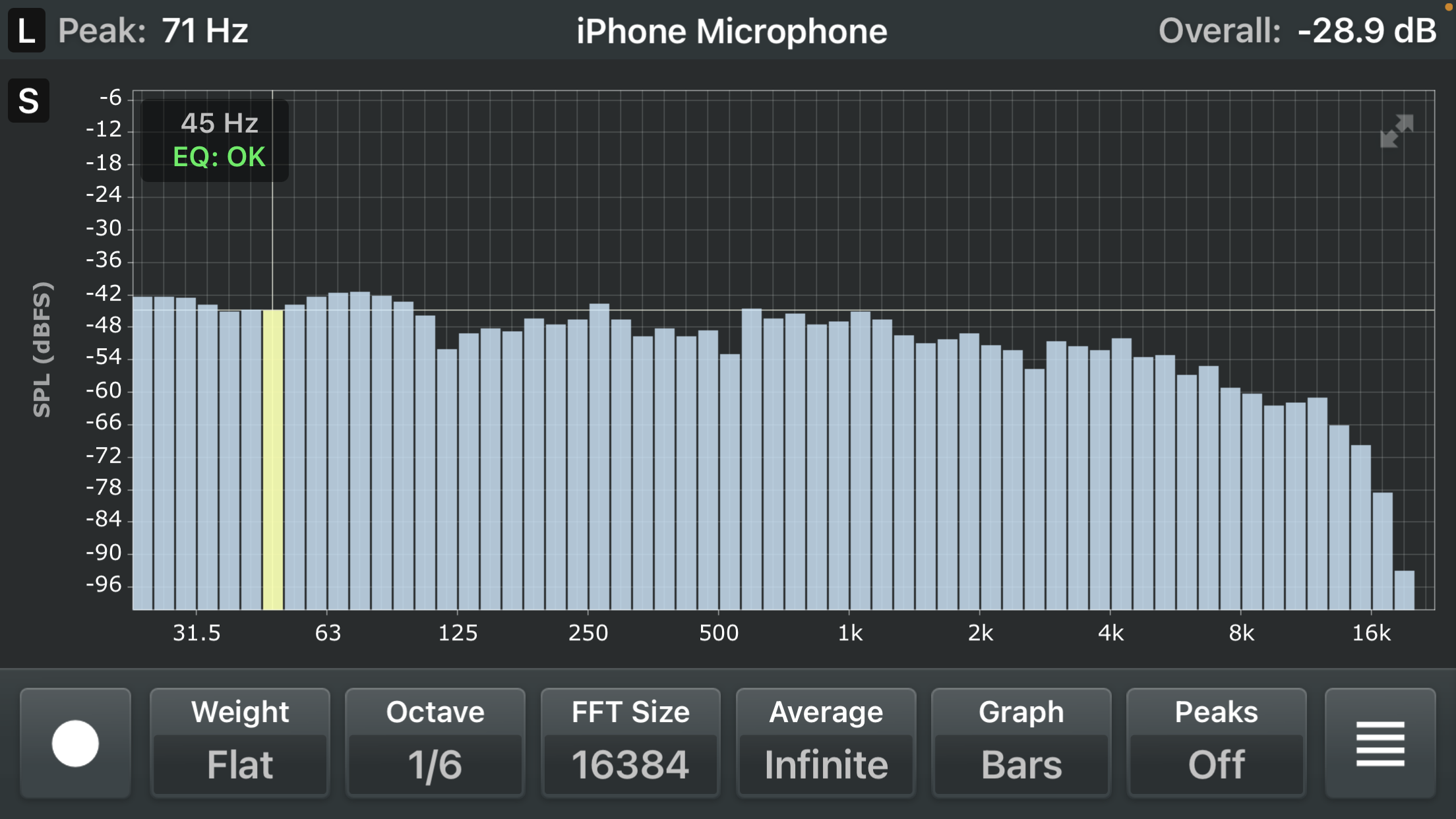
He insisted the disc must be wrong...his system was adjusted to flat, and with my iPhone RTA, I also confirmed it was very flat and there was not apparent rise at 71 Hz where the note seemed to be, when measured at the ear positions. He argued that if the notes sounded equally loud on my system, it was because I had equalized it away from flat.
(I could hardly complain about such arguments since I've made similar arguments myself. But curiously, when I first measured his system response, holding phone at my nose, it DID show a peak at 71 Hz, But moving it back to ear position made it flat.)
I'm not a believer in the resolution of REM, though it's arguably more consistent than the hodgepodge of things I do, so I hardly dare to criticize it either, it's a well known standard. But years ago, when I had adjusted my DEQ using as oscillator to flatten all room modes by ear, it required many high Q notches, and sounded right when it was done. REM didn't show any of that, just some gradual curves. Maybe I wasn't using REM right, or maybe my way of tuning room correction isn't right, but what I do makes sense to me, so I'm going to keep doing similar things.
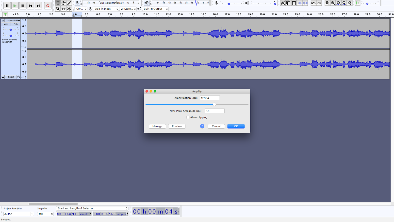
Still, the friend could be right about using this piece of recorded music as a test, I thought. In fact I never before thought to look at Audacity, which indeed shows the third note as about 3.5dB louder than the second. Looking at the passage in Audacity, you can see how the musician winds the relative difference of the third note of the wandering triad down the second time around, so that the sixth note (same as the 3rd) is only 0.3 dB louder. So that's the one to go by. All the following bass notes seem to follow the 5th and 6th in being very close in loudness, but are more blended in with other music so it's harder to tell.
 |
| 5th note |
 |
6th note
|
(Note that the 3rd and 4th notes blend together because of the long tail of the first, and a fair amount of room reverb. So the 5th note is actually the 4th blob, which is shorter but nearly as high as the 5th blob, which I measure by showing how much amplification they'd need to reach 0dB.)
Why did I never think to look at this before.
There also the effect of auditory loudness contours (called Fletcher Munson effect in old hifi magazines) but the third not not that much higher so I think don't think that is much a consideration, maybe another fraction of a dB, depending on how loud the bass notes are played (he was playing them quite loud due to a room curve with a lot of extra bass).
AND there is the open string effect, where the 3rd and 6th notes ring longer. That's not a loudness difference per se though it can sound like one.
Anyway, the test is only decent if you go by the second set of 3 notes, not the first.
Still I think it's useful (though I'd like to make a better one). I have sometimes found the best thing is just to hook my synthesizer straight up to the system and play semitones all the way up. That's more tractable than using an oscillator, you can easily focus on the bum notes or regions, but I haven't even gotten around to doing the self-promised oscillator test I replaced the right speaker in January. (I've been more focused on getting decent movie projection recently.)
As to the equalization of my system, and making the notes sound more alike than they are, that is possibly true.
Firstly, when running just a basic pink noise test on each channel (something I almost never do because it's a pain using the Tact to dial one channel down in 0.1dB steps and back) I discovered something rather critical right away that has eluded me for some unknoen time.
THIS time I finally made audio files with just one channel of pink noise. Why didn't I think to do that before??? It makes this much easier, and especially because you never do just one measurement, there's always one more detail and you have to keep doing them over and over until you get both channels right. (That happened this very time, as it always does, I made my first measurement without the chair position EQ activated.)
And one reason I didn't do that before is that it isn't really clear how to do it in Audacity. When you move the pan slider one way or the other the graph of each channel doesn't change. That had fooled me into believing it only affected the playback output, not the audio file generated. But this time (with encouragment from google AI) I tried it and it worked, so I finally made left and right pink noise files.
Anyway, I quickly discovered the right channel had no deep bass at all! I wondered if the AC cord had come lose again, but no. In fact, the issue was that it was actually turned off at the power switch. Because something was being moved in or out the front door I turned it off before disconnect the power cord, which projects near my entry area, then I reconnected the power cord, but I failed to turn it back on.
This reminds me of a story my audio friend George likes to tell about the onetime tube guru of San Diego, "Ike", who I once worked for. In George's telling its a sign that Ike, the supposed golden ear technophile, who self published a but (the Tu-Be manual, which I have a heavily annotated copy of) and the Audio Dimensions monthly flyer, couldn't hear worth shit. George visited Ike at home and Ike's system was playing out of phase.
Well, in these regards anyway I have some sympathy for Ike (who quit his audio hobby shop business not long after I left, with a new wife, leaving his former mother in law, who'd paid for the business from the first minute, in care of the store for its remaining 2 years of operation, which did have one fantastic Audio Society meeting--the very one where I first went with George.)
I often have music playing in the background, and I'm not always paying attention to every aspect of it. That the way listening works. We don't make a mental model of everything, only that part of the musical experience we are paying attention to, which could be the shimmering of the extreme highs, relatively unaffected by phase. To really hear out-of-phaseness, you minimally have to be listening in the sweet spot, and even then it may be tricky to hear on some music.
Anyway having the left channel sub off eliminated one potential source of muddiness and boom, possibly even making it sound cleaner, while not actually affecting the level much, and that can easily be compensated for in many ways, turning the volume level on the emotiva dac decoding the bass digital signal is what I usually do, though I've been generally keeping that at the usual -8, I see it's now at -7.5.
So now I'm looking at both channels, and there do seem to be some issues in the right channel, whose panel speaker was recently replaced with a different Acoustat 2+2. I was going to sweep that to fine tune the bass, and I never got around to it, so here I am with a slight bass suck out, but it's entirely below the -71Hz apparently involved. Anyway all recent comparison listening is invalidated because I had one sub off, I'm going to have to listen to Spanish Harlem and everything else all over again.
Anyway, here are the (incorrect) measurements at the listening chair without the listening chair EQ (aka "boost") turned on. I was pleased at how flat the bass is even without turning on the boost, with both channels playing, though the bass at 71 Hz and below is a bit anemic, though I think this is exaggerated by the 1/6 octave bands, this is actually a very flat response compared to most systems up to about 1kHz where I deliberately roll it off, the correction above 1kHz was determined by ear with a chairside EQ, I believe this kind of curve is warranted with dipolar speakers in a medium small medium reflective room, with a larger room needing less roll off due to diminished reflections.
 |
| Both Channels, at chair, no boost |
Now, the left channel, which hasn't changed much in quite awhile, looks even better, basically flat in the bass until around 40 Hz where I let a bit of the room gain back in for a more solid sound. This is what I call "electrostatic bass" where the bass is nearly flat except way down low where a bit of exaggeration helps. You can't see at all where the subwoofer crosses in (very steeply at 125 Hz) or any trace of rear wall reflections.
 |
Left channel, at chair, no boost
|
But the right channel, which I knew needed readjustment since I replaced the right Acoustat, looks much worse, a suckout in bass between 40 and 71 Hz. This would weaken all 3 of the first bass notes in Spanish Harlem, not just the 3rd--which is nearly back to baseline.
 |
| Right channel, at chair, no boost |
Now, what I actually hear in the bass is more like the Both Channels graph, since bass that deep is inherently heard without stereo localization. A big weakness in the right channel yields a small weakness in the combined response, and that's usually fixed by adding the boost. Now lets look at the boosted responses.
The boosted response in both channels is almost a perfect example of "electrostatic bass," flatter than I've ever measured any other speakerup to about 1khz, but just slightly turned up (rather than rolled off) at 20 and 25 Hz. There is still a little bit of the irregularity caused by the mis-EQ of the right channel still visible however:
 |
| Both Channels, at Chair, with Boost |
Even with Boost, however, the right channel still shows a characteristic lower bass depression:
 |
| Right Channel, At Chair, With Boost |
Now, before showing you the weirder than weird EQ behind this, let me explain...
What looks "ad hoc" is only partly "ad hoc." Initially, all EQ's are dialed in with precise manual oscillator sweeps. I hone in on the worst response peak, and then try to cancel it out with EQ notch, generally the steepest EQ that seems to get the whole peak. Then I repeat that process with the new worst peak.
Then later, with RTA measurements and listenings, I sometimes tweak the adjustments a little, mostly raising or lowering the notch levels, only sometimes by very slightly changing the frequencies (which I generally don't do because those were originally precisely dialed in). Sometimes the oscillator comes back out for new peaks or re-adjustments too, but not all at once. I rarely start over from scratch, the last time I did that was over 3 years ago.
On top of all this, I add in boost (mostly) with the graphic EQ to get the desired curve after notches have been cancelled.
Now it should be understood that EQ is actually quite forgiving. EQ response changes are minimum phase. Any minimum phase change can be precisely cancelled, or partly cancelled, by another minimum phase change. What this means is that you could have a whole pile of overlapping response errors and EQ's, and if the response is ultimately adjusted flat by all these changes, then the phase has been adjusted flat as well (a fixed delay at all frequencies will be added however).
Learning that transistors, EQ's, and digital audio are perfectly fine done correctly is, I think, an important and very liberating thing.
So I don't mind the pile up so much, though at times (like right now) it can look ridiculous. It usually works pretty well. But errors also accumulate over time, and other system changes don't necessarily get the full readjustment they need. So it IS probably time for another from-scratch readjustment.
 |
| Parametric EQ, Right Channel with Boost |
 |
| Graphic EQ, Right Channel, with Boost |
What about that weird pile up of notches near 100 Hz? Well, looking at the response with all EQ's turned off, something like that is clearly needed:
But it also looks like many of the notches below 100 Hz aren't really needed any more, if they ever were. (But note that RTA is not the whole story, it's a kind of averaging which obscures the finest of peaks and valleys, which are only visible with something much finer like an oscillator sweep.)
Now before delving deeper, it would be good to look at the individual panel and bass responses too (that has messed me up many times). I'm leaving the midrange and up EQ's on the panel since I'm just adjusting bass today. But I tried the right panels with and without the bass EQ (with the bass EQ the panel response looks "more ideally crossed over"). Here is the panel response with the bass EQ:
 |
| Right panel, with full EQ |
This looks pretty much like a very steep crossover should. The response below 100 Hz is mostly room noise. I may have tuned this to be like the other speaker when I changed the right speaker.
 |
Right panel with no bass EQ
|
Without the EQ, the response right above the 125 crossover point looks weak. What is this EQ? It's being done with the graphic EQ:
 |
Bass EQ for the right panel
|
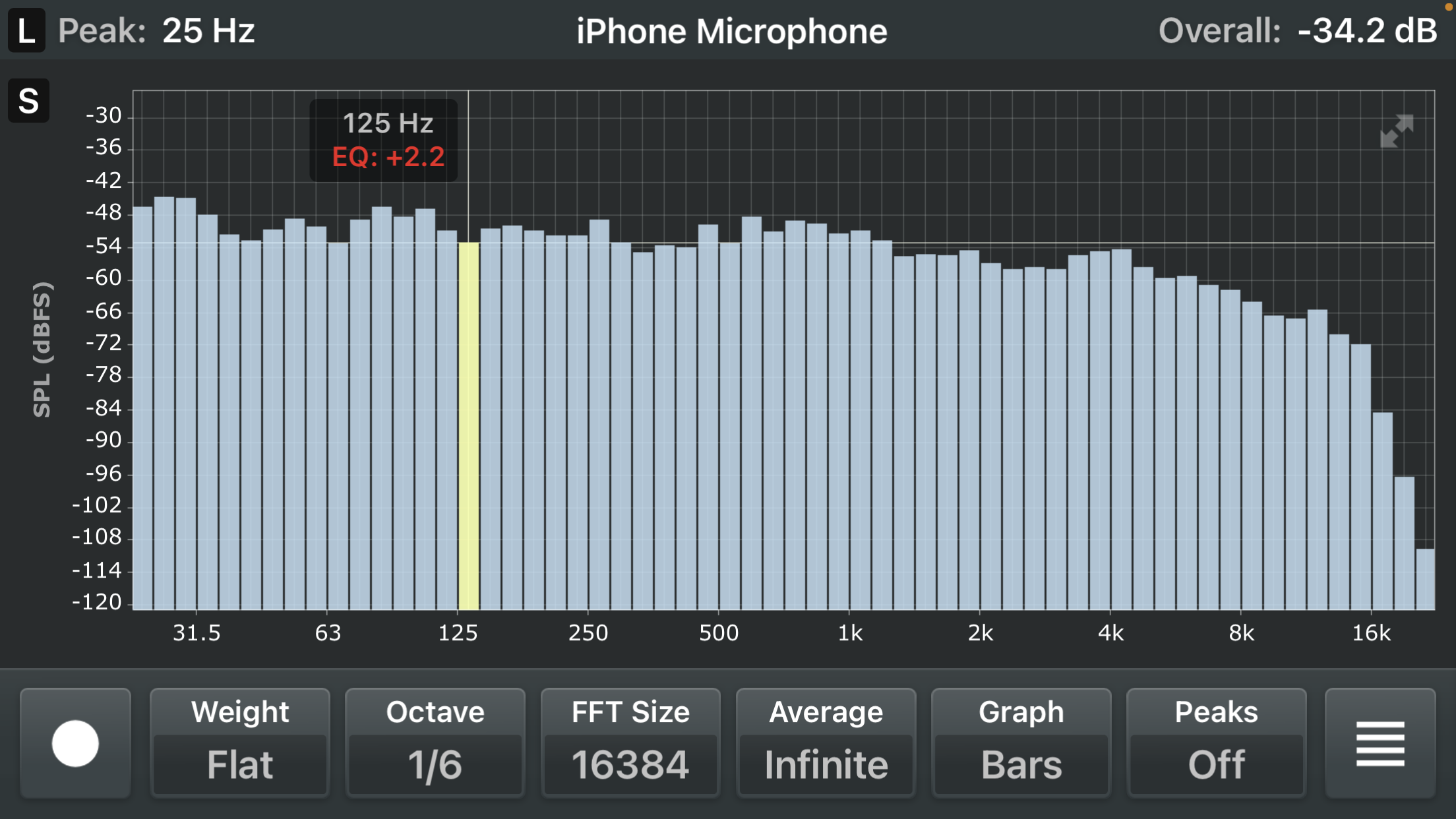
It's a 6dB boost at 125 Hz (curiously or coincidentally the crossover frequency) with a bit more boosting above it and just the tiniest amount below.
In the overall response, it doesn't look like this boost is needed. (Though, looks could be deceiving.) There is minor peak at 125 Hz in fact. However the crossed over panel response looks much better with it, otherwise the response is too weak at and above the crossover frequency. I think I should keep this boost because of that.
Meanwhile, the crossed over sub response shows great peaking at 100 Hz, just below the crossover frequency of 125 Hz. If the sub/room were flat, the response at 100 Hz should be just over 1dB below baseline (because of the crossover) not way above it. The response at 125 Hz should be 6dB down (because it's a Linkwitz-Riley crossover with both sides in phase, and also phase corrected).
What is going on around 100 Hz ??? I will need to break out the oscillator to investigate, since this is almost certainly a combination of peaks which the RTA at 1/6 octave resolution obscures, and probably much like the weird pile of notches I dialed into the bass EQ.
Oscillator sweeping with my Tek CFG250 (my latest in a long line of great oscillators, with the previous ones all now dysfunctional and needing repair) which sadly lacks the vernier microhertz resolution (in output, the reading was always off by Hz) of the General Radio oscillator I need to fix, but is far nicer to use than any oscillator I've had before, gives a somewhat different picture.
Basically there are clear high Q resonances from 135 Hz down, next 120, next 100, 80ish, and more. Above that the crossover is in deep cutoff. All those need to be fixed (I'm hearing them even with the crossover). Then if it turns out that suppressing some of those weakens the output, I might dial back the notches to fill in the overall response. However, I do not like that idea anymore in general. When you have two speakers, I believe you must cross over. Otherwise you are going to have comb filtering between the two sources, and therefore a very high degree of position dependency. A touch of eq in the panels is better than letting the sub output at higher frequencies. (And in fact I was doing far more than just a touch already, and probably wrongly overall, but as a quick fix for the new panel on the right side.)
So this is the method: identify each of the initial resonances by finding the high Q notch that most effectively removes them. THEN one by one remove them with right sized notches.
Update:
Tonight I'm only finding 3 big resonant peaks (probably from room modes) all around 100 Hz. I tried to stimulate the 250 Hz resonance (I had to go to the next band on my Tek oscillator) that appears on the RTA, but I could not hear anything there. The three "exact" frequencies, determined by nulling them out with my DSP, are:
126 - 127 Hz (the null is equal for those two frequencies)
93.5 - 94.6 Hz
71- 71.8 Hz
In both cases, the separation is very close to 1.33, which is 4 semitones ("a perfect fourth").
If that were the actual bandwidth of the resonances, they'd be somewhere in between 1/3 octave and 1/2.
My "method" was supposed to be sweeping each resonance to determine the optimal notch bandwidth. That's tricky here because each resonance is piled on top of another one.
I think instead I'll start with the assumption that 1/3 octave is correct for each of them and see how that works.
*****
Well, as I should have known, it's madness. Once I try to cancel out the resonance at 127 Hz, say with a 1/3 octave notch and -3dB, now another peak appears pretty much exactly at 100 Hz, and it becomes dominant. Then I do that one, and the next peak moves down to 91 Hz or thereabouts. Once again, this seems to be recreating my original weird filters.
So I've always just done these one at a time, never trying to map them out in advance, and that appears necessary still.
And I'm not sure if starting from the top is the way to go, but it seems like a good way to start.
Now I find on closer examination, even with no EQ at all, I get an actual null around 120 Hz at the listening position. Moving the big chair back seemed to make little difference, so I replaced it with a directors chair. Then I could get way from the null starting at about 1 foot further back, with diminishing returns after 2 feet.
But then I did a sweep from 2 feet back, and it appears there is a different null around 37 Hz. Moving the chair back up to the standard position, that null goes away.
The 120 Hz null is unaffected by either the 127 Hz notch or the 100 Hz notch. It's a null and it aint goin away, probably because it's room mode related. It's very narrow however, I'm not sure how musically significant. Also the panels may have some output at that frequency. The 37 Hz null further back is wider but probably less musically significant, but panels can't help, and it always irks me to have weak bass between 30 and 40 Hz (something I've often struggled with).
For now, I'm going to stick with my close up wide angle presentation, and live with the 120 Hz null, otherwise I'll have to readjust everything. I'll just ignore the narrow null at 120 Hz but try not to make it wider, and see if the panels help.
That's the kind of thing that's rarely visible in RTA type measurements. Very high Q nulls, but wide enough to show up on sweeps. However very high Q nulls may be musically unimportant because real music is rarely pure sine waves, there's vibrato, echo, and all sorts of things that prevent getting those nulls. Pure sine waves are like laser beams, they behave differently than natural light, but are very useful in some ways.
I set the filters to 127 Hz, 1/4, -3.0 and 101 Hz, 1/3, -7.0 after some ad hoc listening and iphone measuring. I noted that at some frequencies near 100 Hz it was indeed very sensitive to position, and especially so at the null. I don't use sine waves because I want to find the nulls. If you have infinitely fine control on the oscillator, you could ultimately find infinitely many nulls. I use sine waves because unlike pink noise and MLS techniques, sine waves reveal the deep resonances which are also illuminated by sustained notes, and those deep resonances are what tell you how best to tune parametric filters (IMO).
Suckouts on the edge of each notch led me to use the narrower 1/4 octave filters on both, but perhaps I was just being spooked by the null about which I can do nothing electronically.
After setting up a trial set of filters, I'd sweep the with the oscillator and notice anomalies. The narrow notch filters seem to do their job, but not to be able to handle the adjacent peaks very well, even if I make them quite wide. But I never formally tried to notch out the whole 100 Hz peaking with one wide filter and see how that works, which might be worth trying.
I'm thinking I really need a chairside EQ to do these adjustments most easily. Getting down on the floor for each touch of the EQ, and when I often need to go back and forth, is just too time consuming. I use a big foam pad for my knees, so at least it didn't make my knees hurt.
***** Update July 16
I now have an early version of the chairside bass EQ for testing purposes. It's not the permanent version because there is no way to go back to the bass EQ except by changing cables. I'm getting another optical cable delivered tomorrow so I can change back to the normal EQ by flipping the input on the bass DAC to coax. Both EQ's will then be running in parallel, and I will be able to switch from one to the other.
I was going to do this with AES cables, but my cheap AES splitter is hard to find and my expensive one, currently unused, is plugged into the power strip behind the FM tuner and digital recorder...it would take at least a whole day of equipment moving to "extract" it.
Time for testing is limited in the next few days (and beyond) but I did a quick test of putting a wide (1 octave wide) "notch" at 100 Hz. It was clear I needed to make this notch about as deep as I could. At -15dB, it may be only slightly too deep. It's remarkable how much better it makes the 1/6 octave curve from the Analyzer app. Almost right, but still a kind of dip between 70 and 30 Hz.
This is what someone with the most primitive octave EQ might do. If anything, a correction recommended by REW might be more (instead of less) complicated. Maybe I should see what REW would recommend!
There doesn't seem to be a need for incredibly narrow notches like I was doing before. Yet (and without having done any very fine oscillator sweeping, just a quick spin and RTA). Perhaps wrongly, I continue to believe in the need for very fine and "deep" (slow) scanning. RTA like these images just blurs all the very fine detail you can hear with an oscillator, or even a keyboard (another nice test). (FFT, MLS, and Impulse techniques all lose both the resolution and the deep resonances shown by very slow oscillator sweeps.) I've seen similar gradual curves in the bass, which never seem fully explicative to me, from all software I've ever used (LAUD3, REW, Tact, and others) even the one I wrote myself (gfft). You rarely have enough "bins" to get good resolution in the bass. Whereas, with a sine wave of sufficient duration, you can get whatever resolution you can dial in.
 |
| Right Sub, No EQ |
 |
| Right Sub, -15 at 100 Hz at 1 octave |
But RTA can put me in the correct adjustment ballpark if I already know the notch frequencies from slow sweeping, so I'm going to try that. (Otherwise, hunting around for the correct adjustments is madness, as they all interact.)
Do I know the correct frequencies? I'm not sure whether you determine the correct notch frequencies first going downwards (as I did in the last few days) or from nulling the worst error(s) in turn (as I've always done before....I fix the worst peak and move on to whatever is left over). This is an opportunity to test those methods, and maybe others.
I'm not sure how programs like REW optimize the filter(s)... When I looked at the documentation it was not at all revealing about such things. If you say they merely invert the transfer function (which I don't believe REW does, inverting the transfer function is too finnicky), then the question becomes how is a model transfer function fitted to the measurement data?
The issue is that apparent peaks may not be the true peaks, but shift as a result of other peaks, and so on.
From that vantage, it would seem like the biggest peak would be the least affected by others, and therefore the place to start. (Going downwards is another way of starting with filters less affected by others.)
But starting with the highest peak, which may be virtually buried in the detritus of a larger lower peak, how do you know when to quit?
It's that line of thinking that before led me to starting with the biggest peak. That's what I've done with 100 Hz above. The 1 octave bandwidth looks fine (doesn't cause excess losses on either side) and -15dB is all I can do with one PEQ (though I could add a second...) on the Behringer DEQ.
Well at this point, with -15dB, there's still another -10dB or so needed, and that's still the biggest thing, so I'm going to start with that.
***** Update July 17
After the last RTA photo showing -15 at 100 Hz, I dove into a series of measurements with different added second filters. But the usual madness set in, and I neglected to keep notes about what every measurement was. And before I was done, I couldn't remember.
All along the way it seemed almost every change made it better. But looking back many of them actually look about the same. When you don't know the baselines, and can't see the curves overlaid, it's hard to tell what it should be looking like--there are many different possibilities as will become apparent.
So I've had to go over the same measurements again. If I make it -30dB at 100 Hz using two -15dB notches, it looks like this:
 |
| Right sub, -30dB at 100 Hz at 1 octave |
Smashing down 100 Hz with two notches reaching -30dB looks good in a certain way. From 125 Hz down theres a rising bass "room curve" which looks plausibly useful. There's no more depression between 40 and 60 Hz because everything higher in frequency has been smashed down sufficiently.
Looks may be deceiving. 125 Hz has been squashed enough that the steep crossover above doesn't do much, because it's already at such a lowered level. If I just turned on the panels now, there's be a depression around 125 Hz. But then I could crank up the sub level by 20dB or so, and I'd have the room curve from hell (or heaven, perhaps). Though perhaps it's good that the room curve would then stay flat until just below 100 Hz before rising pretty steeply, then the rise helpfully slows down until the very bottom.
This looks plausible in these ways, but I think it's probably wrong. The goal consistent with my "electrostatic bass" target concept would be a 6dB rise going from 125 Hz down (the Linkwitz-Riley crossover) and then level. The measured curve should not be fairly level just below 125 Hz, that's where it should be dropping the most sharply, then the decline should stabilize. Well it is stabilizing, but only below 63.
So I think the room curve below 125 Hz is mostly too steep, and gets steeper exactly where it should be leveling off. On the other hand, the flatness between 40 and 71 Hz might be harder to achieve any other way. Otherwise it's going to need "boosting" (as I was originally doing with my chairside EQ which this is intended to replace).
(Yes I do worry about why it needs such a large and wide notch at 100 Hz. I presume it's a bunching of room modes, reflection/additions, and things like that, though I often worry if the now 15 yo subwoofer is really working as designed. But it's not making any untoward sounds other than caused by the curves shown.)
It looks useful to try total reductions less than 30dB, such as 25 and 20dB, and then back to -30dB (since that was done last night) as a sanity check.
(These measurements are only ballpark because I don't have the a stand for the iphone, I just hold it at approximate right ear position. Also I may adjust the level from time to time, I somewhat increased it this morning to show better resolution and less effect from ambient noise. Also, probably with no difference, I switched to Sonos ZP80 instead of Oppo BDP-205 as digital streamer, which should make no difference.)
I think -25dB looks very different, and better than -30dB. Now the bass is fairly flat from the crossover down to the (still present) depression around 50 Hz.
 |
Right sub, -25dB at 100 Hz, 1 octave
|
 |
Right sub, -20dB at 100 Hz, 1 octave
|
I think -20dB looks barely different from -25dB. In either case the 100 Hz bulge is completely gone and there's a plateau from the crossover frequency down to about 63 Hz. (All that's being determined is the exact height of that plateau compared to lower features.) I think I'm going to choose -20dB as a starting point on the "less is more" principle, and see how it works with the panels (perhaps I can drop the +6 at 100 Hz in the bass (which, btw, is in the GEQ not the PEQ because I like to use gentle GEQ's for boosts).
Anyway, it's still very important to see how it works with the other driver, not just solo. In principle I could also re-adjust the crossover, but that is way too complicated at this point. (I generated a FIR linear phase crossover on my mac back in 2021 and loaded the coefficients into the minidsp. It's not just a knob I can turn.) Anyway I think the crossover is more or less "correct" and getting it right is very complicated. It's LR8 at 125 Hz, and I think it's phase linearized to acoustic crossover at 125 Hz, which still seems to be the case, or is it?
Now it's bothering me that it's not rolling off -6dB at 125 Hz, as it should be doing with an Linkwitz-Riley crossover. It only starts rolling off higher.
I notice that before I obliterated the 1 octave wide peak at 100 Hz, it seemed to start to rolloff at 125 Hz, but that may have partly been an artifact of of the wide peak starting to roll off rather than the acoustic crossover (by "acoustic crossover" I mean where the drivers ACTUALLY cross over, one get louder than the other etc, as compared to where you set the electronic crossover, which doesn't fully describe the acoustic crossover because all the various cutoffs and resonances in the driver combine with the electronic crossover to produce what you can actually hear and measure, which is the Acoustic Crossover).
So maybe I got the acoustic crossover all wrong before and now it's just being exposed???
(Truth be told, I don't remember what acoustic crossover I used for the FIR crossover I generated, that determines not the levels but how the phase is linearized, following my method of linearizing to the acoustic crossover and not fine measured details like most others do.)
It seems to me that peaks in the driver response would push the acoustic crossover higher, and dips would pull it lower, not vice versa.
But there's also being fooled by the apparent rolloff of a lower peak into thinking THAT is the acoustic crossover, when it isn't, which might have happened here. OR ???
Actually, another interpretation is that there IS a peak, which I am not correcting for, which IS driving the acoustic crossover higher. And that is the peak around 127 Hz. I am flattening that peak only by (perhaps excessively) flattening the 100 Hz peak, but the 127 Hz resonance is still there, driving the acoustic.
So before measuring combined response, I should check how it currently sweeps with the oscillator.
Sure enough, the 127 Hz peak and a 141 Hz peak are still there. I ad hocly more or less flattened them with -3dB, 1/6 octave notches. Adjusting those notches probably will help set the acoustic crossover lower where it should be. I had notches like that before...
BUT, if I'm going to compensate for lower panel output at 100 Hz by making more output in the sub, then I will axiomatically be driving the acoustic crossover higher, which is fine except that then I should re-generate the FIR crossover filter with the new acoustic crossover so that the phase linearization is correct.
(My feeling is it's not important enough to bother yet, maybe in a year or so when I'm pretty happy with whatever bass alignment I've come up with.)
Tonight I'm going to have to move the right sub to allow a new water heater to be brought in and the old one taken out. So these experiments are shortly going to be suspended, to be resumed later.
I should see if I can still hear that peak by sweeping with my oscillator, and then try to correct it and see if that fixes the acoustic crossover.
****
In addition to the 127 and 144 Hz resonances, a 71 Hz resonance was unearthed by sweeping (it was barely visible on the RTA too). There was no trace of the 91 Hz resonance I detected before nulling out 100 Hz (though it might still be there with a slower and more careful sweep, now probably unimportant anyway).
The circa 117 Hz acoustic null (with a small suckout around it) is annoying but seems entirely related to geometric considerations, changing EQ does not affect it at all. Now I notice that it goes away when standing up. It doesn't so much go away when moving the position deeper back into the room by a foot or two, I only thought that because when I tried moving back I was standing up. This suggests it's a floor ceiling mode. One plausible fix might be to cover ceiling with dampers the way my friend has done (but I can't afford it and don't want to for other reasons). I see that the wavelength of 117 Hz is 9.6 feet, that's almost exactly the peak height of my vaulted ceiling (which vaults not far from right above the listening position. Perhaps just damping the vault of the ceiling would help. (I would have expected the resonance to reflect the average height, not the maximum height, and that a vaulted ceiling would not produce a near perfect null, but perhaps that's not right, maybe you get the best (worst) nulls with a ceiling that vaults just above the listening position.)
Running some more numbers, I see that 71 Hz is the wavelength of the front to back length of the room, about 16 feet. The width of the room, 13'1", doesn't correspond to the other peak I measure, 91 Hz, but rather to 86 Hz, but it looks like 91 Hz is the nearest 1/6 octave band (my method of determining frequency is really determining which parametric value I can dial in to best cancel it, otherwise it's a pain to keep a frequency counter connected to the oscillator while doing the measurements, way too many wires in my lap. And I figure, this is the value I really need, since I'm going to be dialing it into the PEQ, so might as well use the PEQ numbers.
So here's what I know:
Room width: 13'1" 86 Hz (close to 91 Hz PEQ frequency)
Room length: 16': 71 Hz
Room max height: 9ft: 126 Hz (very close to 127 PEQ frequency)
Each of these in fact has a peak in the frequency response which I am now correcting with a tiny EQ.
But where does the massive 100 Hz come from??? And why the suckout around 117 Hz ?
It's not even clear to me why I should get tiny peaks in the frequency response at wavelength frequencies. Reflections cause a fixed pattern to emerge, and that fixed pattern could either have a null in the center or a peak in the center, and I thought (wrongly I now see) that the null in the center was more common.
I know there are some lower modes where the round trip wavelength is important. That's what must be the case for the 45 Hz resonance it seemed (and possibly in the other sub) I've had to struggle with the most, and for the exact reason that it nulls in the center near the listening position, and peaks around the periphery of the room. So if crank up 45 Hz to get some response at the listening position, now the whole room is rattling because of bass at the periphery (and amplifier power is being wasted, and dynamic range lowered). It's this exact issue which led me to have a "Background EQ" which attenuates 45 Hz and other frequencies, and a "Listening Position EQ" which doesn't or does less.
(The way that used to be achieve was that I'd made one EQ which was at least OK for the background, then add in boosting with the GEQ for the listening position. Crude but it worked. Bu now I'm back to scratch and see I simply don't have to cut 45 Hz at all for the listening position EQ, so I won't have to adopt such crudity at least in these cases)
Now it appear that 45 Hz corresponds to two room widths, just like 91 Hz corresponds to one room width. So it looks like at dimensions which are 1/2 the wavelength, we get just this problem for a center listening position: suckout in the center and excess at the periphery. And it happens the 45 Hz one is for the room length, so what are the others:
14'1" x 2 = 28' 2"... 40 Hz...yes indeed I have struggled with this too (usually dialing up 39 Hz actually)
9' x 2 = 18... 63 Hz...yes there is a minor depression there too.
In fact, these last too minor depressions are exactly what showed up in the characteristic pattern that launched this investigation. The are half wavelength modes, the length one which is fairly neutral at this listening position (but causes boom elsewhere).
But still no explanation for the biggest peak of all, at 100 Hz, and the weird null at 117.
*****
I've now looked at a variety of sources including wikipedia, GiK Acoustics, Sweetwater, and others pulled up by Google.
None of them give a good explanation of how room modes work, IMO, starting with the basic question, is the lowest one where 1 wavelength is equal to some dimension, or 1/2 wavelength (because then the round trip would be one full wavelength).
But now that I've stated it this way, I think the answer is obvious. It's 1/2 wavelength, and it's because precisely by the time the sound has made one full trip, across some dimension twice, it's back to where it started. That's how you get standing waves, which is what room modes come from. Now the same thing is true at multiples of of 1/2 wavelength, such as 1 wavelength, but before long absorption has an effect so that eventually the higher numbers become unimportant.
Now, this basic fact is buried in the formulas used by some articles, where they use a factor of 2 multiplied by some dimension, etc. So that just what I said in the previous paragraph, though it's turning it around in a weird way which nobody seems to want to do, I guess because I'm thinking about wavelengths and they're talking about about frequency. Unusually for me, I guess, I'm seeing it as in my mind (though maybe only in 2d) whereas they're giving you number like some calculator would, but sort of disconnected from any diagram or other 2d representation which sort of explains why it works.
F = c/2 * sqrt(p^2/L^2 + q^2/W^2 + r^2/H^2)
This completely obscures the fundamental axial modes, which is what an idiot needs to understand first.
Lets just look at what this simplifies to for the lowest fundamental axial mode (p,q,r = 1,0,0)
F = c/2L
All that square root and power verbosity goes away. If I were writing the textbook, I'd start there (or actually with my bit about wavelengths, which turns it around:
2L = c/F
Now it almost looks like the powers on the p's do some real work for the higher order axial modes, where for example p = 2... But no, it's just a gimmick again, the second order F simplifies to (tada):
F=c/4L
So it seems to me a computer programmer (as I was) or a mathematician would have some better way for doing this calculation than all those powers followed by a root, when the output is just a simple linear inverse with one factor (c/2).
Where all* that stuff suddenly becomes necessary is when you have axial and oblique modes, and those cannot be so easily simplified because you are taking the square root of a sum of squares rather than just one. They don't mention how to get to the ultimate "oblique" modes, but it's clearly when you have all 3 terms operating, so it's the square root of a product of 3 things...related to LxWxH.
(*I think the powers related to the pqr terms remain unimportant if unfolded differently, just as in the one dimensional case, but I haven't got the patience to work through the math. Those are trivially calculated. You're going to need the powers and square roots for the 2 dimensions themselves, so the programmer in me would go to the big formula at this point anyway, only one sqrt needs to be done in any case.)
Ok, I've sort of explained it to myself now, it doesn't seem like anyone else does a good job. And Wikipedia is taking a very audio partisan position (with notes that it needs to be rewritten). Some things are not practically handled with absorption, because the absorption needed at low frequencies inherently becomes very large. In a tiny listening both perhaps, because the modal frequencies are very high... But not in an ordinary listening room.
(So now it seems there is a method to my friend's madness with a tiny room. But my feeling is much like Linkwitz and others...it just feels wrong. It feels right to have a big ordinary room, reflective but not too reflective the kind that you would have a conversation in. That's what's nice for listening to music. For recording music...go ahead with your closet and practicable absorption at low modal frequencies.)
My friend George moved into a big new house in 2000. He had a dedicated and slightly isolated listening room. It is way bigger than my living room, with a ceiling that goes up to something like 20ft. He had 3 circuits put in by a mutual friend (who worked on my house when I lived in San Diego). He had his enormous stacks of electrostatic and bass speakers, driving by an array of amplifiers.
It had been refined through 2 previous addresses. But he simply gave up on it. Never sounded good (I only remember it as sounding fine, just like before) he said.
He found he preferred a pair of inexpensive AR speakers, with the smaller one on top, played in the living room, and later with some drivers disconnected, and ultimately with the top one replaced by the Radio Shack RCA speaker with lineum tweeters. But not there, in the much larger living room, which is open.
He insisted that it was because this new approach, of giving up on the big pile of electrostats, etc, and going to a pair of hacked cheap speakers, was a superior approach (and superior in everything else in the world too, by his reckoning and as my occasional experience too, everything was differently hacked every time, and he always had the best of the best music. Sadly, in his mid 80's he gave up on audio, and it's been noted his hearing wasn't as great anymore either.
But I've always felt it was...the much bigger room. Anything would sound good there. It was in such a big open area, it would be several times the size of my entire house (and connecting to the downstairs through a big open stairway too.
When you can push the room modes down to 5 Hz or so, well who cares. And vastly delated and attenuated reflctions. And it's quiet too, mostly.
So anyway, I do have smaller scale system in my other rooms. But I never much liked the idea of the "pile of speakers" apprach, though it was my own standard back in the day. At some point in the early 1980's I had a pair of ML-1's (heavily hacked into subs) and (more and more hacked) LS 3/5 A's (I still got em, but they're barely the same speaker, I was using them as super tweeter boxes most recently...but I have all the parts...I got them cheap and now they're worth big bucks...but for the longest time they were the foundation of my system, combined with ML-1 bass.) The ML-1's had blown non-bass drivers and bypassed everything and reduced stuffing but I donated them so I hope they've been restored now. They were never that great as subs, actually. You got lots of upper bass harmonics rather than the deepest bass, even with the EQ. When I moved on to real subwoofers for my satellites I never looked back.
Plus, my superlative Pioneer Series 20 D23 four way crossover developed hum. It looks so beautiful and has such high end parts I though it would never fail, but then I ultimately figured out that the ever increasing hum (long blamed on the Mac 225) was actually coming from the solid state and seemingly immortal Pioneer D23. It's awaiting refurbishment in my overflowing shelves of pricey but not quite perfect gear.
Anyway, once I started using digital EQ, I never looked back from that either. Not only could I use the vastly superior and flexible LR4 crossover (sometimes called LR24 because it's 24dB per octave) but I could very precisely dial it in to any frequency and level. The D23 did also have precision controls with 1dB and 1/3 octave settings, but not as fine. Plus it was impossible to read them mostly. I usually just counted the clicks as I was turning the knobs. Anyway, the D23 only had LR2 which is far less useful than LR4 and always requires a phase reversal in one way.
Now, using an FIR filter generated by Rephase loaded into my miniDSP, I can have LR8 (48dB/octave) and fully phase corrected, something that's simply impossible to do in the analog domain.
(But wait, I thought, minimum phase and all that. But that's when your restoring something to flat, not when your cutting it off. When cutting things off, minimum phase will always have the largest phase shift, which you get back only if you bring the frequency response back again. If you want to have the frequency response change, and especially if you want a steep cutoff, with no phase change, that requires magic which can only be done in the digital domain with FIR filters. Ordinary crossovers, with the usual minimum phase phase shift, are IIR.)
On the other hand, if you are more sophisticated about your speakers and if your subs have built-in DSP eq, then you can get a small room to "work" by dealing with the higher frequency modes, which are also more amenable to acoustic treatments.
I see small rooms as an interesting "challenge," not that I'd wont to use one except for performance, and none of my rooms are all that big either.
Speaking of which, I should start with the correct measurements, which I just redid, and they are:
Length 187 inches 15.58 ft
Width 157 inches 13.08 ft
Height Max 108 inches 9 ft
It should be understood that numbers like these are only a simplification. The room not be perfectly square, and ceiling for sure is not flat it's peaked. Then there are open doorways, and window sills, and furniture. What results from all this is not necessarily all that close to what a room simulator tells you, for example, here.
Before I delve into these numbers, let me also point out it that they don't directly say what you should expect to hear at any given part of the room. They sort of tell you what class these modes are, but not how important they are going to be.
Also, if they seem unfamiliar to me, it may also because once again I'm used to using the nearest frequencies on my RTA or DEQ which I use to null them, which are not the actual frequencies (and I keep having to remember now that they are not).
So this great calculate tell me the axial modes for my room should be:
36.11
43.02
62.52
That showed a big gap, and absense of room modes, around 100 Hz.
That can't be right. So then I refigured the effect of the peaking room. Instead of counting it at the highest height, in the center of the room, how about the lowest height, which is close enough to 8ft that I'll just use that.
Height: 8 feet
Then, the last axial mode becomes:
70.33
And is further reinforced by the 2nd harmonic of the first axial mode, at 72.23.
This is beginning to look more like reality, with a kind of peak appearing around 71 Hz by PEQ frequency.
I should remember that this does not PROVE the correct number to use is 8 ft instead of 9 ft for the height. Actually no one number WILL give the correct answer, but I could not figure out how to make changes in the 3d model they provide for an arched ceiling. And then the doorways, windows, carpets, furniture, and all that.
This does also show a peak very close to 100 Hz, the 2-0-1 type, a kind of tangential between the length and the height
But I notice that small changes in one dimension move all the higher order (tangential and oblique) modes around a lot, much like chaos. Changing only one dimension affects one set of axial modes and only in a commensurate linear fashion. So this high sensitivity suggests to me that the higher order modes are less predictable without exact measurements, total rectangularity, and accounting for furnishings and other details.
Essentially the only way to know where the modes really are is to measure them. The models may or may not help us figure out what each measured mode is.
So the 100 Hz mountain still doesn't have a clear explanation, except that it does not appear to be a simple axial mode but some combination of axial and higher order modes, possibly including 2-0-1.
**** July 19
I'm still dumfounded by how I kept thinking, for 32 years, that my living room was 14x16. It's actually 13.1x15.6, as I determined by actual measuring tape yesterday. I think I'm settled on the room dimensions now, anyway...though I haven't measured from the other corner, which might vary if the room is not exactly square.
And then now, as I was calculating (guesstimating via a wavelength calculator) mode frequencies, and scanning for modes with my oscillator, and getting different frequencies each time.
And I think my computed modal frequencies matched observations, but the ones from the website did not.
All that made me feel like I was in the Bistro in a Hitchhikers Guide book, where the waiters aren't cheating you, but mathematics itself is changing, the most powerful force (or tool) in the universe.
I get that feeling a lot, and mathematics often seems to be conspiring against me, now cutting my living room down by over a dozen square feet.
Let's go back over those measured vs computed modal frequencies.
Yesterday, I finally got to figuring (from the ridiculously long full formula which includes tangential and oblique modes) what the basic axial modes are:
F = C / 2L
What is C? The speed of sound, 1130 ft/sec.
Now it should be easy to go from L to F (instead of reverse guesstimating from a wavelength app, I can just calculate the exact numbers.
1130 / 2 * 15.6 = 36 Hz
1130 / 2 * 13.1 = 86 Hz
1130 / (2 * 8) = 71 Hz
Well now math has changed again, and these numbers ARE what the app came up with for those measurements. 71 Hz is a direct hit on what I measure, 86 is close enough to the 91 Hz that sometimes (though curiously not so much now) appears. But the primarily bothersome room mode (at least when emitted by the other speaker) is not 36 Hz at all, it is 45 Hz. Here it's fairly neutral though. And then the worst thing of all, the 100 Hz boom which I'm cancelling out with 20dB of attenuation? Does it really all come from one 2-0-1 tangential mode???
I confess I've long worried that is some issue with my now 15 yo subwoofer itself. It was the top SVS when it was new in 2009. SVS has replaced the plate amplifier for free several times (I've never paid them for any such replacements). But I've always wondered, is the woofer still working correctly?
But how would as issue with the sub make in 20dB louder at 100 Hz??? It would seem to me, mostly, it is designed to put out as much sound as possible, and any fault would make it put out less power, not 20dB more, out of the blue, just like that.
It seems to me, but perhaps I'm wrong. One scenario might be that it's actually working correctly at 100 Hz, it's just wrong everywhere else, something is choking off the power. But in that case, how is it so easily putting out room shaking bass around 20 Hz, when much larger excursion is required.
So it doesn't seem like a subwoofer fault, could cause this kind of problem, but just to be sure I'd like to point it out the doorway and measure outside.
And it seem like I could do that, now that I've moved the subwoofer out of the way for installing a new water heater. But actually (and contrary to much thinking) I simply cinched the sub up to the wall rather than moving it across some distance such as into the hallway which is some distance out of the way but not at all in the path of the plumbers moving the water heater.
So I'm not actually in any advantageous situation compared to normal as far as moving the subwoofer into the doorway, really. And I worry about imperfections in that test, the house is still operating as a resonator around the sub in through the upper part of the doorway unless I can block that off completely, which would not be easy. It would be best of all to take the sub to an open field. But I can barely move it inches without dollies, sliders, etc., and I don't want to damage it either.
Another kind of test would be to move another loudspeaker into that position. I have other SVS subs, but they would be a pain to move too, and technically I should move the original sub out of the way too, so there goes the "advantage" of testing that way.
But I think it's worth trying without moving the sub from it's cinched position. I could barely squeeze a small speaker into the location where the SVS cone was firing, therefore kind-of duplicating the test with another speaker, and seeing if the 100 Hz also emerges.
So I think I will do that particular test, but there are many forthcoming external activities, so it will take some time to do it.
But the easiest thing to do, which I just now did, was to check the SVS settings.
And yet again there was confusion, because I have two SVS subs. And after finding that I'd wrongly set the ports to Standard (and being surprised that I actually had two ports open, I must have made that change sometime, but still registered it in my mind that my mind that it was sealed, I had to loosten the metal grill which is nearly pinned on now, and feel the ports with my fingers, to believe that I had most recently left two ports open) and it needed to be set to Extended, since I now apparently have two ports open.
So what about the other sub? I apparently haven't enabled the bluetooth on that one or it might not even have bluetooth being an earlier generation, but I think it does since it's not that much earlier. But it also has the knob and menuing system, which it operates through now. I'd have to check the display, which I have no need to because it seems like it's measuring flat in the entire left channel system, "Electrostatic Bass (like)." It was the right channel which seemed weird, though I eventually might want to do some tests on the left too, but I only have about 2 weeks left for testing, and many other things to do.
Anyway, this could explain some of the 100 Hz boom. It won't change the real modes, but it does sorta change everything, because a barely explicable 100 Hz boom dominated everything else, so I'll have to start from the raw measurements again, since the port tuning could have been responsible for that and many other things throughout the sub band. And this time I'll try to do the measurements somewhat better, using an actual stand for my iphone (which just arrived). So New Math. But not so new as to go to microphone, interface, computer, program and all that, but it's a good step.
Apparently when I got the current replacement interface for the right sub, which has only been replaced that one time since 2009 and I think it was less than a handful of years ago if not just 2, I failed to reset the port tuning correctly. Ohboy, shades of Legendary Ike again, sub set wrong for years. But I compensated with lots of EQ.
*****
To see what the room response at the subwoofer position looks like, but with a different speaker so I can be sure the 100 Hz peak isn't some kind of subwoofer error (though it might be party explained by the port tuning misadjustment), I put a Revel M20 speaker where the sub usually is (and on the floor too). The sub itself is right next to it, pushed right back to the wall. (It's hard to move the subwoofer or I'd move it completely out of the way, obviously having it there could affect the results.)

The Revel M20 has virtually flat response, rated +/- 1dB from 46-16000 Hz. (I'm going to ignore the fact that John Atkinson's measurements in Stereophile show a hump around 100 Hz because John Atkinson's speaker measurements always show that hump because of his methodology. He doesn't mathematically "correct" for the kind of error that adding two responses from his room together causes, feeling that such correction would not be accurate for any one room. And he's always done it that way, so the responses of all speakers he's measured can be compared to each other. Though it is interesting that 100 Hz also regularly appears as an issue for him too.) So any peaking I measure with the M20 is caused by the room response.
Measured on the floor at the sub position, the Revel M20 also shows peaking at 100 Hz but it looks quite different. What we see is a broad plateau from below 100 Hz to 355 Hz, returning to baseline at 400 Hz. This plateau is marked my little spikes which represent some room modes: at these frequencies 100, 140, 280, and 355. Below it there are another two modes visible at 40 and 71 Hz. (All much like the room mode simulation I did using ceiling height of 8 feet.) With all this going on, it still appears like 100 Hz is the highest response point (along with 140 Hz which is identical).
 |
| Revel M20 on floor at right sub position |
The analyzer app says that 100 Hz need 9.6dB of attenuation. But compared to what? Compared to 1kHz, it needs about 13dB attenuation, and compared with 50 Hz (the lowest "flat" response of the M20 speaker), it needs over 15dB of attenuation (note the recommended EQ are -9.6 at 100 Hz and +5.8 at 50 Hz, which differ by 15.4dB). Compared with 31 Hz, it needs about 19dB attenuation (except the Revel has started to roll off there). So that's similar to the 20dB attenuation on the sub which brought 31 Hz and 100 Hz to the same level.
 |
| Revel M20 at right sub position, marker at 50 Hz |
The reason why I don't see the broad response plateau between 100 and 355 Hz with the subs is that they are crossed over at 125 Hz. So I just see the lower 100 Hz peak and that is all.
What causes this broad plateau? It could be some kind of melding of the 100, 140, 280, 355 Hz and other modes. But there could also be some kind of resonance in the room in those frequencies. I'm suspecting this is showing, at least partly, a "sheetrock" resonance. In fact I do feel the walls vibrating in a way which would be consistent with it (though that could be effect rather than cause).
Anyway, it seems the subwoofer itself has been exonerated from causing the 100 Hz peaking. I see a similar thing with my unimpeachable Revel M20.
I'm now wondering if this kind of response would be visible in another location, such as next to the listening position, or with the Revel up off the floor, though there is no way I can keep the subwoofer in such positions.
*****
The pattern of bass boom shifts considerably when the speaker is kept on the floor but moved to a position as close as possible to the listening position along the bookcase along one wall. The peak is no longer 100 Hz, instead there are lower and higher peaks. But there is still a lot of extra room gain unhelpfully between 80 and 355 Hz, so this is not better, maybe even worse.
 |
| M20 on floor adjacent to listening position |
When the speaker is kept at the subwoofer location, but turned upright on its stand so that the woofer is at ear level, the 100 Hz boom improves at least halfway to perfect. So it appears a lot of this boom is related to the "corner" position. (It is in the corner of the living room, but that is an open corner to the entry way and the hallway that goes to the bedrooms. So I'm not sure how much like a corner it is acoustically. But as far as coupling to the entire room at low frequencies, it is very much like a corner.)
 |
| M20 at ear level near sub position |
I would only need about half as much EQ if I were to somehow move the subwoofer up on a 3 foot high stand. This is a barely imaginable thing to do for this 155 pound subwoofer.
But thinking about it another way, this boost at 100 Hz actually means I can power the driver less for the same output with EQ. It is therefore, in principle, giving me more dynamic range. (Except for the spurious and harmonic noises produced by the room and walls this way.)
People put some speakers and subs in corners by design, to take advantage of the extra "room gain." Some speakers and subs are designed to work that way and only that way. Their design (effectively a kind of physical EQ) compensates for the predicted frequency response of corner placement.
McIntosh made corner placement tuning the default for the ML-1 full range speaker, with boost as required for other room locations with the MQ 102 equalizer. In some cases those bass boosts were quite large, approaching 20dB. You probably couldn't actually use those large boosts with very deep bassy music, such as some electronic music, at loud levels.
If we don't fear using EQ (and I do not anymore) we can do the same thing with any speaker, even if not designed for corner placement. Any speaker can be EQ mapped to any kind of room location, but ideally (unlike MQ 102) you'd need to enter the room dimensions too, not just the type of placement.
And be aware of headroom limitations. I do use two kinds (both frequency independent and frequency dependent) limiting in the subwoofer eq, that is one of the really cool features of the behringer DEQ 2496...one hopes that subwoofers have some kind of internal limiting so as not to be easily destroyed...but often it's better to limit far before that to do so gracefully, and also to avoid excess room noise
It seems the SVS has some sort of room gain thing I should check out.
But aren't corner placement "coupling" and "room modes" different things? I'm thinking they may be related somehow. And it seems as well as coupling to the room best, corner placement also couples to tangential and oblique modes best, those modes get a big boost by corner placement, which is why they are sometimes (such as in the Wikipedia entry, which needs rewriting mostly) said to be most important, but I don't think that is true so much when speakers are placed out by about 1/3 the length of the room from the walls, only for wall, edge, or corner based speakers.
It looks like the SVS room gain compensator is only for the lowest frequencies, such as 20 Hz and below. It's just a high pass filter. There no way to cut out a plateau of room modes not at the extreme low end. Little beats real parametric EQ (except perhaps thousand plus pole FIR filters, and they're much harder to use on present equipment, or locked into proprietary systems you can't change except in authorized ways).
I remember when (analog) parametric EQ's were very rare and I lusted after them, like the one made by SAE. Then I had one for a bit, and found it just didn't have enough poles, 1/3 octave equalizer better. But those are incredibly difficult to use, especially when dual mono. With digital EQ we have very fine readable and repeatable settings, the likes of which I could hardly dream in my youth. And any combination of parametric and graphic EQ (and often Crossovers and FIR filters and limiters) we want.
I have parametric EQ's in 3 different DSP devices I have in sequence, but I only actually use the parametric EQ's in the Behringer DEQ 2496 because they are the easiest to change (with knobs, buttons, and displays, instead of having to hook up a computer). The Tact also has parametric EQ, and the miniDSP's.
***** July 23
Here is the "explanations" for the AMCoustics room mode calculator. Much much better than the GiK Acoustics explanations, this is the best I've seen so far, and starts from intuitive concepts.
It does point out that the first mode is half wavelength, so the counts in the index specification (such as 2-0-1) are the number of half wavelengths, not the number of full wavelengths. That clarifies what was unexplained by other sites I had visited previously while writing this article.
With a simple axial mode at index 1, there is a null in the center of the room, and peaks at the walls. In index 2, there is a peak in the center of the room, dips to either side, and peaks at the walls.
Except in higher order modes, you don't get dips at the walls, so much as I have already observed, the bass is heaviest at the walls.
The modes are absorbed best if the absorber is placed in high pressure area. Likewise, a mode is stimulated best if the source is placed in a high pressure area.
With the 2-0-1 resonsnce, the wall in front of the longest room dimension (that's my front wall) is divided by the tangential mode, with high pressure on bottom and low pressure on top. Then, what happens is the peak pressure goes to the ceiling in the center of the room.
This exactly corroborates my findings. The 2-0-1 mode is stimulated because the sub is on the floor in the front of the room. For 2-0-1, it doesn't matter that it's also in the corner. (I strongly believe there is also an oblique mode operating here which makes the corner worse, but the calculator doesn't show such an oblique mode.) I could reduce the peaking by moving the sub up so that it's halfway between floor and ceiling, in between the high and low pressure zones.
There's not much I can do about this by positioning, it's totally impractical to raise the 155 pound and huge subwoofer up 3 feet.
There *might* be something I could do with absorption. 100 Hz is a high enough frequency that absorbers aren't totally impracticably large. When you get to the low frequencies, below 50 Hz, suitable passive absorbers become so large as to be totally impractical unless you can dedicate a substantial fraction of the room volume to them. I wasn't previously aware that there was a serious mode problem as high as 100 Hz before. Of course it wouldn't be stimulated by the Acoustats either if I were crossing over lower than 100 Hz, which was doing a few years back. (The Acoustats will not stimulate the 2-0-1 mode much since they radiate across low, high, and middle pressure zones of this mode.)
EQ is by far the easiest solution. And what are the real (as opposed to imagined) problems with EQ?
Well, mainly that you can't EQ the entire room when there are modes. But you can (mostly) EQ the listening position, and with a bit more slop, you can EQ the listening position and a few other nearby positions by keeping them from getting too bad.
In this case, lower crossover frequency for the subs might also help. But that would reduce headroom because the Acoustats have resonances from 125 Hz down, and these resonances cause bottoming and other issues at higher levels. The reason I use a 125 Hz crossover are:
1. The acoustats flap, bottom, and rattle when called upon to do bass below 125 Hz at high levels. They aren't very accurate in this region either because they rely on resonances to extend the apparent response to 40 Hz. Yes they do 40 Hz, but it's not true electrostatic operation it's membrane resonances at 40-45 Hz and 80-100 Hz.
2. The subs stimulate more objectionable 100-240 Hz room modes when they are crossed over above 125 Hz. (Actually they already stimulate the 100 Hz resonance with is fairly objectionable, so on that score it would be better if I crossed over the subs even lower, but I do use a steep cutoff to help.)
I think I've already optimized the crossover frequency as much as I can, my living room is a multipurpose room also used for movies and general entertainment of self and friends and not suitable for much more re-arrangement or massive absorbers.
***** July 24
Tried out new iPhone holder for my microphone stand and held precisely at right ear position for testing right sub. Sadly I forgot to switch Analyzer app to flat instead of C.
Doesn't look to bad with the first set of PEQ's I came up with from sweeping and pink noise tests.
I decided to do another more dedicated set of sweeping tests to find all that needs be found by this method and get everything adjusted so at least it "sweeps" well.
That took a slight lessening and narrowing of the 100 Hz suppression, and a few more notches going up to 144 Hz where despite the crossover (and working well) there's a section that sounded boosted compared with what is around it, and down to 38 Hz, with filters now at 38, 42, and 93 Hz.
This is sort of looking like before, but has all been redone from "scratch," I didn't refer to anything done before. Today I actually used a frequency counter, well my Fluke 8060A, attached to the DEQ analog output. But I couldn't always get a reading when there was a lot of attenuation being applied.
Though some of it's pretty ad hoc. I sweep for a peak, find the frequency and notch it enough to sound about right. I start out pretty narrow and make it wider if it needs more, or narrower if it's depressing what is around it. All the tiny fractions like 1/4-1/7 are just guesses really and could possibly be widened or narrowed slightly. My general idea is that it's better to be narrow and small, if that works. But super narrow might be a problem so I avoid 1/10-1/8 except for testing purposes or they seem necessary.
Also, even with a very very slow hand as probably only I can do, there's not much resolution in this plastic Tektronics oscillator. I can barely eek out 1 Hz resolution, usually it jumps around 2-4 Hz. So that makes it really hard to set these filters, and contributes to considerable uncertainty as to whether or how much they are incorrect.th
I identified three rattles and fixed one for now.
Around 20 Hz, where the walls are shaking a bit, and I'm permitting a bit of "room gain" which may come from a whole house resonance of some kind, a rattle to the left was the new motorized blinds. After trying to damp various parts of the assembly, I realized the rattling was coming from the plastic termination of the blinds rattling against the wall. By repositioning the "upper" position of the blinds to just below that point, and slightly but only slightly visible below the valance when all the way up, I was able to defeat this resonance. As usual I flailed with the open control for minutes before deciding I needed to find the (nearly impossible to read small print) manual. I used the new reading light I put in a week and a half ago on the back wall of the listening room above the loveseat. (Finally, a convenient reading light that doesn't always have to be taken out of the room because it's in the way.) And I had to track down my 1.75x reading glasses and give them a wipe with my new lens wipes.
And then I could see, but still probably won't remember next time, that I need to move the switch out of User and hold down the upper button for 2 seconds (at least) until the motor moves twice. I thought I was holding it down, but I guess not for 2 seconds.
Another resonance was from the plastic "thermometer" on the wall which measures the outdoor temperature with an RF link (which is currently flaky because the outdoor battery terminals need cleaning probably if not replacing the batteries). I've put various kinds of stick felt and such on the back but they always come off when I replace the battery. This time I put some electrical tape, which padded the contact point with the wall. Just a piece of electrical tape was sufficient for this one.
But there's a another resonance coming from the tile beneath the fireplace mantle. This is a very depressing situation I may not be able to ignore forever, though I seem intent on doing that. The tile is bunching up and projecting out like the bow of a ship because of possibly several things including the foundation needing more leveling. It looks like it will fall off any second, but feels pretty solid. Eventually when it falls off there will be all kinds of materials from the wall covering my equipment. Maybe if I covered it all in duct tape at least when it collapses it won't be that bad, but then I'll still have to clean up the duct tape goo. Anything other than a duct tape fix would require moving all my equipment away from the wall. Which will take days. Not to mention putting it all back again. And what do I do then? This is beyond my capabilities, all the tile needs removing and re-cementing. And maybe none of this should be done until I've installed the next round of piers to support my foundation better, because after that it may need doing again.
Now it sounds pretty good by sweeping. No big peaks jump out any more. Everything that did jump out has been trimmed back to baseline. Nulls I cannot fix with EQ, there's that big 113 Hz null at the listening position that is unaffected by any of these EQ's, it's just positionally nulled out. I'm not aware of any other nulls but if I had much greater resolution and patience I could probably find some.
Speaking of which, I was thinking I'd get better results with my Sound Technology analyzer, which has 1 Hz pushbutton resolution. But it's not easy to remove from the pile of equipment it's in.
So, now, if this still isn't flat, I either adjust the EQ's small amounts and/or add boosts with the GEQ where it can help.
And then, after I've got this looking good, I see how it meshes with the panels, which might require a lot of things to get reworked and/or eq's be added to the panels.
Analyzer was now showing something like ideal response, nearly flat but still with a small apparent depression around 36 Hz.
 |
| Right Sub after full sweep adjustments |
I tried and tried getting rid of that depression by removing the cuts at 39 and 43 Hz or by making them narrower. It didn't work very well, I had to sacrifice much more peak suppression than was gained in flatness at 35 Hz (the 1/6 graph doesn't show the narrow peaks at 38 and 42 Hz).
 |
Narrowed filters around 40 Hz take one
|
Actually this particular response looks pretty good, but I cannot remember what the filters were set to. But I still felt that the peaks in the swept response were not acceptable.
Here are the later narrowed filters (actually the 39Hz notch is canceled completely):
And here is the response that corresponds to that (and now I felt the response wasn't good enough):
Here are the normal version of the filters:
It was looking to me like the normal version of the filters would work best with a boost at 35.8 Hz at some width to fill in the depression. Octave width tended to raise the surrounding features so the valley between them remained. Narrow widths worked better. I ended up with a 4dB boost and 1/2 octave width:
.PNG) |
| Right sub with 1/2 octave boost at 35.8 Hz |
This shows a plateau around 35 Hz...it could not be better than that. However, there's a slight dropoff at 45 Hz, perhaps that filter can be narrowed again.
After some fiddling with the filters at 39 Hz and 43 Hz, I was able to get impressively flat response aside from the room gain below 30 Hz.
I'm going to call it a day right here before I mess this up again. Damn it looks good. Sweeps pretty good too. Downside is I've ended up using every single PEQ available in the DEQ. I would have preferred not to need boost but every other finished result I've done so far uses boost, and this is as simple and low Q as it could get, 1/2 octave at 35.8 Hz. The previous version used 6 or more GEQ sliders with boosts up to 6dB, and wasn't anything like this flat.
 |
| Notches around 40 Hz readjusted, with 4dB boost |
*** July 25
I first measured the Right Acoustat by itself (no sub) with the 125 Hz crossover, getting this:
The region right around the 125 Hz crossover looks very good. I boosted the level just below the crossover to help fill in the modal null at 113 Hz in the subwoofer. The tall planar speaker does not stimulate the 2-0-1 mode. There's some irregularity around 250 Hz and above but that has nothing to do with the crossover or the subwoofer.
I then measured the full range response using the original "boost" EQ. (I forgot that I was using the original EQ because I've switched back to the original DEQ unit today.)
 |
| Right channel, original "Background" EQ |
Pretty lumpy in the bass, just as it was when I decided a re-adjustment was needed. But now I noticed that the bass dips would go away if I just boosted the sub level by 3dB, so I tried that:
 |
| Right channel, sub boosted 3dB |
Now the bass is seeming pretty strong, but wait, I forgot to set the "Listening Position" EQ, which also boosts the bass. Doing that I got a very "powerful" if slightly uneven bass:
Bass was overwhelming now. I didn't much need that 3dB boost.
But this wasn't what I intended to measure at all. I wanted to see what response I'd get with the new subwoofer EQ I've been developing. Now it was time to take a break.
Later I got to work copying the new filter constants into the DEQ normally used by the bass. What I've been doing is making a new version of the Listening Position EQ (stored in memory LISTEN) for the right channel (since it was not up to snuff due to recent changes, among other things). So I first backed up the original LISTEN in position 2 into a new memory labeled L23 (meaning LISTEN from 2023). It turns out that different memory slots have the same name, and there's another LISTEN stored almost at the end of stored memories. Yes, that's the one I stored when I started this project, but a bit of redundancy is ok here. I can easily see when memories are exactly the same because when one of them is loaded, and you select another one in the memory function, the "MEMORY" light goes out because it is identical to the current one.
When I combined the new sub EQ with the Panels and their old EQ, and the now 3dB increase in sub level, I got this:
 |
| Right channel, new sub EQ, plus 3dB |
Now the boost I added gives it way too much bass. It looks like old bass EQ needed a higher sub level to produce the same output because of some redundant and overlapping notches. I reduced the level back down to what it was before today.
 |
| Right channel, new sub EQ, plus 0dB |
Sub level could possibly be reduced another 1-3dB. There's still a depression if not a suck out at 113 Hz. There's a broad rise around 90 Hz
As I play a lot of very bass heavy music, I've learned that it isn't really a good idea to have boosted bass, because it limits how loud you can play. So really heavy bass such as on Bass Erotica, one of my favorites, forces you to turn down the level so the words are barely audible. So my goal is basically "flat" bass response.
I often call my listing position EQ "Boost" because some of the bass is boosted relative to the background EQ (because many places in the room have louder bass than the central listening position) but the result is supposed to be flat response at the listening position.
As compared with previous EQ adjustment marathons, this time I've had chairside EQ and oscillator to hear how it actually sounds at listening position. Previously, I often did lots while sitting on the floor next to the EQ, only occasionally getting up to listen or measure at the listening position.
AND starting yesterday, I've been using an iphone stand mount, so I can keep the iPhone in the correct position (which I've decided should be right ear position for adjusting the right speaker, though I will choose a central position when I'm doing both channels).
I had hoped to give more of a blow by blow for the setting of each and every PEQ, but I still don't have patience for that.
**** July 26
Given there is a raised regions below a crossover frequency, as shown in the last right channel spectrum, there are two ways to proceed:
1. Lower the signal amplitude being send to the lower frequency driver, and then raise subsequently depressed regions with EQ
2. Cut the low frequency raised regions with EQ
This choice has always confounded me, and I have no better solution now. Any kind of fixed rule (such as make the drivers exactly equal at the crossover point) has cases where it doesn't work as well as something else.
To my eye, what's happening in the right channel combined response probably needs a bit of both approaches. I may lower the level AND lower the raised regions below the crossover point with EQ. I might even have to raise the boost around 35 Hz just a bit (though I had gotten that flat when playing the sub by itself, or at least I thought. While doing the current investigations, I discovered that when the refrigerator in the kitchen runs, I get raised bands at 63 Hz and adjacent. This may have contaminated my measurements in curious ways. The "flatter" response might well have been taken when the refrigerator was running, boosting that region slightly. But I first noticed the issue while measuring the panels by themselves. There was sharp rolloff at 100 Hz caused by the crossover, just below 100 Hz response was quickly at the noise floor, except when the refrigerator was running there were these curious peaks in that noisefloor. Now I'm going to be paying attention after making any measurement whether the refrigerator was running or not.)
One key thing, however, is investigation. We ought to figure out why some regions are higher than others, and see if that guides us to the best solution.
Right when I started using the newer black fabric Acoustat for my right channel, I determined right away some corrections were needed to my Acoustat equalization. I'm not sure if this is the only thing I did, but the main thing I did was to add a boost (via 1/3 octave GEQ) of 6 dB (!!!) at 125 Hz (!!!), the crossover frequency. I didn't like that idea at all, but it made things work. Well, I'm in the same situation now. With the boost in place, 125 Hz is already a bit weak and there's still a depression at 113 Hz. Maybe whats needed is a boost specifically at 113 Hz. But that wouldn't fix the broad rise centered around 90 Hz. My hopes and dreams of EQing the subs so as not to need a boost in the panels around the crossover frequency are not looking good.
Here are some detailed questions that might be worth investigating:
Does overall response look better with 1-4dB of further reduction in sub level? (My preliminary guess is that about 2dB would be optimal).
Can the depression at 113 Hz be cancelled by boosting the panels there?
How do the left and right panels compare by themselves?
How does the elevated bass around 90 Hz sweep?
Would removing the tiny sub notch at 127 Hz reduce the need for boosting 125 Hz in the panels?
But just as a kind of sanity check, I compared the unweighted SPL (iPhone app measured) of the subs on left and right channels. (I measured this with mike in dead center of the listening position. Having a stand for the measuring device is essential to doing this measurement with any kind of accuracy, and I've never used one for the iPhone before this week. It's also extremely helpful to have separate left and right pink noise tracks...as on my system it takes minutes, often down on my knees, to get this changed...ah how I long for the old style preamp controls for my digital preamp: Stereo, L, R, L+R mono, and L-R mono. Because it was such a hassle, I rarely did individual channel measurements before, and of course they are essential to investigation and getting things right.)
Left Sub: 71dB
Right Sub: 72dB
This already suggests a 1-2dB reduction in right sub level might be warranted. How about the panels:
Left Panel: 68.7 dB
Right Panel: 70.7dB
Now it looks like "raise the right panel and lower the right sub" looks like the right approach, even before messing with EQ (which could make it worse). But how loud do the panels "sound". Check the A weighted levels:
Left Panel: 66.5dB
Right Panel: 68.0 dB
Yep, raise the panel and lower the sub. How did this ever sound balanced before??? I'm going to first try doing both at a mere 1dB, which looks like the minimum that might be needed.
The bass I can easily do with the SVS app. I changed the level from -10 to -11.
The panels...are a problem. The Behringer DEQ 2496 does not have individual channel level controls (and a lot of similar things like polarity controls...I suggested these to Behringer in 2019 and within a year they discontinued the DEQ 2496 with no replacement in sight...that sort of thing happens to me whenever I make suggestions...it also gets to weirdness in Intellectual Property Rights...merely buying a DSP chip doesn't give you the rights to use it in every possible way in a commercial product...you may have to pay fees to license each kind of DSP operation you use or market you are targeting...and the DEQ was sold as a mastering processor not a Room EQ device so perhaps they didn't take kindly to hearing it was being used as a Room EQ device...but I'm sure they already knew this and I doubt they worried about it and it's probably just coincidence this time...except it's probably why they didn't include more features in the first place).
In theory I could make this adjustment either in my Tact Preamp or in the miniDSP's. It's a pain to change the miniDSP's because I need to attach a computer and be sure I don't wipe out the previous stuff by mistake. It's easier to do it in the Tact but I frequently forget about those settings and in the past I always used the channel level adjustments (buried in a menu item) for just muting right or left channels (you have to run the controls all the way down from 0.00 to -99.9 and that's why muting one channel has always taken so long in the past.) Also, if I do the level fine tuning in the Tact, it won't apply for background FM music which bypasses the Tact, but I'm not going to worry about that.
Then there is another issue. I cannot "raise" the level of the right channel in the Tact level menu because it's already at 0.00dB. I can only lower the left channel to -1.00 to make this relative difference. But then I have to raise something else.
Plan A:
Lower left channel to -1.00 in Tact level menu.
Raise Emotive Stealth DC-1 level (driving panel amplifier) by 1dB
But actually I cannot do this, because I've already raised the level of the Emotive to +11.5 and +12 is as high as it goes.
Last year, before I killed the Hafler 9300 playing a shorting Acoustat, I had the Emotiva level at +6. But because the Aragon 8008 BB has 5.5dB less gain, I then needed to raise it to 11.5 to keep everything the same.
Then I also worry that the Emotiva is going to start distorting with a full level signal at 12dB if not less. It's not specified and no review I've seen actually tells the maximum output level of this Dac. 12dB of gain from the standard 2V output would be equivalent to 8V output (single ended). It's probably OK, but I've determined the maximum undistorted output of the Emotive XSP-1 is only around 6V, and it uses the same opamps (but different other circuitry).
I should never be driving the DAC this hard actually. I only set things up this way because the miniDSP's use an ASRC, and their ASRC is prone to inter-sample-overs. In the investigations I previously did on this, I wasn't sure where the inter-sample-overs peaked, it seemed like it might be as high as +4.5dB but I thought it could be as high as +6dB. So I allow 6dB extra headroom by attenuating the miniDSP's by 6dB (which seemed to eliminate the inter sample over problem) and then raising the gain of the DAC by 6dB. It should never actually go to that +6dB level for any real signal, only microsecond peaks caused by the ASRC. (I have complained bitterly about this before. The real solution is to have fully synchronous digital everywhere in a digital chain. But the audio industry has decided I don't need digital processing, only a DAC, and for DAC's an ASRC is sufficient if not optimal.) I should only need about 5.6V output to drive the Aragon 8008 to double it's rated output, which might be ok for a transient.
Anyway, Plan B would not involve raising the DC-1 level any higher.
Plan B:
i) Lower left level by 1dB in Tact level menu.
ii) Lower left and right sub levels by 1dB (easily done in the second DC-1 used for the subs).
ii.i) (added later...see ii.i below, must also raise left sub level by 1dB in it's plate amplifier.
Add-on Plan B+ (just to lower panel DC-1 level from insane +11.5dB):
iii) Lower Panel DC-1 by N.
iv) Lower Sub DC-1 by N.
Assuming the DC-1 has about the same MOL as the XSP-1, N should be at least 2dB to bring the level down to +9.5dB (about 6V) which is also a good peak headroom level for driving the Aragon (for transient ISO peaks that will probably never happen).
It might be useful to actually measure the MOL of the XSP-1 myself, but my bench is full and it would take an afternoon to do it. Meanwhile these numbers just look good, and it was working fine before, but N could be as large as 5 without too much loss in headroom.
Larger reductions in DAC gain mean that for the same output level, a higher level digital signal is required (if possible without digital clipping), and if this reduces needed digital attenuation it preserves more real resolution. OTOH, if digital amplification is required, there's basically no change in real resolution by these means. I normally listen with 4-12dB of digital attenuation so this would be resolution enhancing. OTOH, only a certain amount of digital amplification is available to me, in the Tact, and I sometimes need it.
So I'm going to compromise at N=3 to add resolution without limiting potential gain too much. Here I not that when playing through Roon there is usually reduction which means that digital gain will not cause clipping. But to be sure I should check Roon to see how much attenuation it is applying (for the Album Leveling that I use). I can safely apply at least that much gain if needed.
(I've probably been making a mountain out of a molehill here. When the Tact digitally attenuates, it matters little because it sends a full 24 bits to the next digital device. So what's being lost is the full 24 bit resolution. So for example 6dB of attenuation means it's now "only" 23 bits, which is still way more than needed. Still better avoided, but not at significant cost to convenience).
So I've done this, Left level in Tact is -1dB, panel DAC adjusted downward from +11.5 to +8.5, and sub levels down from -8 to -11 (because part of this was to change the relative sub-panel balance on the right, with left channel trimmed in the Tact). Normally there should be the exact correspondence between lowering panel DAC and sub DAC.
It's ideal to have the Tact apply 0dB of digital attenuation then no resolution is being lost, OR if Roon is already applying digital attenuation, it's ideal to have the Tact apply digital gain in an equal amount. But for practical listening usually a bit lower is used.
Oops, the part ii of Plan B doesn't work as intended. What it does is lower both subs, so now the left sub is lowered 2dB while the left panel is lowered 1dB, they are not lowered by the same amount.
WHAT needs to be done is to correct that with a new ii.i:
ii.i) Raise Left Sub gain at the plate amplifier by 1dB.
THEN the gain of the left sub isn't changed any more than the left panels, because the change in the DAC level is compensated for at the plate amplifier (on the left side) but makes a relative difference on the right side (which isn't changed until step iii-iv).
I might need to set this back if the panels don't really sound that much different, which I may have been partly compensating for with boost and/or lack of cuts...
I navigated back to Right Sub in my socks, pushing outlet strip out of the way, climbing on to the top of the 3" thick foam pad I now use to protect my knees everywhere, and realized I needed a mirror to see the display panel on the right sub (unless I got rid of the 3" foam...). I'm always stumbling over mirrors, and now one can't be found...
(When I do get up there again , perhaps I should see if this older sub can use bluetooth like the newer one)
Then I realized...I don't need to do it this way....
Plan B (without the addon) should look like this:
1) Lower left channel 1dB in Tact menu (this does sub and panels on the left).
2) Lower right sub via SVS app by 1dB
THAT'S IT. Then I've lowered everything EXCEPT the right panel, which was the intent. So all I need to do is restore the 1dB I took away from the sub DAC (to -11dB now), and subtract another dB from the right sub.
So now the changes made to the two DACs are not part of this at all. I've simply lowered both DACs by exactly 3dB to change the "gain structure" a bit, reducing insane extra headroom.
panel DAC: was +11.5 now +8.5
sub DAC: was -8 now -11
Notice that there needs to be 20.5dB separation between the two, the way things are currently configured, though I could move them both up or down to change the gain structure with that in mind.
Right Sub now set to -12 and left level in Tact set to -1.
It's easy to see I've change the relative sub/panel balance on the right by 2dB in favor of the panels by reducing the sub from -10 to -12, and no other changes affected that. (I could have avoided 3 hours of mental and other gymnastics by just doing that. But it all brought up information I may need later.)
OK, done, now the measurements...
 |
| Sub level reduced by 2dB (wrong EQ) |
The levels look right anyway, look at the impressive flatness from 100 to 300 Hz. But I still have that bulge around 90 Hz and the weird double dip at 40 and 63. I thought I fixed all that in the sub response yesterday.
But that's actually the background EQ, which was cooked up several years ago and hasn't been changed since about March. My home control system automagically sets the stereo back to background EQ when I go to sleep. So the background EQ got reloaded, and I needed to press a button to reload the listening position EQ. That looks like this:
 |
Sub level reduced 2dB, L.P. EQ
|
It looks to me like the sub level could go down another 1-2 dB.
 |
| New LP EQ, sub reduced 4dB (-16 ???) |
I'm seeing that as being too low. Now 113 Hz is in a depression again, and 125 Hz is quite depressed, in spite of the 6dB EQ boost there in the panels. 125 Hz was in a far smaller hole at -12dB (or was it measured at -14dB?).
We'll consider -16 on the subs a loser, but examine -11 to -15 again. (One thing you may have learned is that I make mistakes. There are so many variables involved, it's hard to get everything lined up with an intended experimental protocol. When there's some uncertainty, it's worth revisiting a whole series of things in rapid succession to be sure that only the correct independent variable is being varied.)
Sub levels from -15dB to -9dB. Ignore the EQ recommendations which are not monotonic at all, just look at the curves.
 |
| -15dB |
 |
| -14dB |
 |
| -13dB |
 |
| -12dB |
 |
| -11dB |
 |
| -10dB |
 |
-9dB
|
It's depressing that with the new sub EQ, I need to raise the level to -9dB to get the region from 113-240 Hz as flat as it was with the old EQ at -10dB (meanwhile, the old EQ as about 2dB softer overall because of greater total notch attenuations). It's like maybe I should stick with the old EQ, at least it does the crossover region pretty good (despite or probably because of looking weirder than weird).
It's quite weird because both crossed over drivers are strong by themselves at 125 Hz, in fact, I had to tamp down the sub at 127 Hz (by only 2dB) to fit the intended crossover profile better. The (125Hz/third octave/+6dB) boosted panel has (by intention) higher than profile response to 113 Hz, which is nearly always depressed in the combined response until the sub level is made high enough, which is weird because the sub is perfectly nulled at 113 Hz at the listening position so it would seem that 113 Hz should be more and more nulled as the relative sub level is raised as well, rather than the reverse.
It looks to me like something not entirely copacetic is going on around the crossover frequency with the new EQ. The two sides may not be in correct phase despite my supposedly linear phase crossover. The crossover point needs detailed examination by sweeping before going further. What I think is happening is once the sub level is raised sufficient, it simply overwhelms the somewhat out of phase (or polarity even?) panel. But it shouldn't have to be raised that far, it makes the lower bass just way too much.
It could be something as trivial as the delay being set wrong. The sub is digitally delayed for time alignment with the panels on the axis to the listening position. This was done with the old EQ (or perhaps a similar predecessor) a few years ago. The new EQ probably needs a different time delay. I loathe getting out the computer and microphone to do that, it's a several day project in itself, but I just might have to.
The interaction of the delay and the EQ is one of those reasons why you have to go back and forth endlessly.
Honestly I wouldn't have expected delay to wreak this much havok because the delay times to affect the bass are very large, not the 2-3 ms needed for the sub to panel spacing. But perhaps the EQ's I've dialed in near the crossover point can be dialed down to see what effect that has on the weirdness.
Of these, it's hard to pick a consistent favorite between -11 and -13 so I might settle on -12 as initial value. Once additional negative EQ is added to suppress the bass peaks (and another of my questions is why they are even appearing when the bass by itself was much flatter) it will lower the sub response, possibly bringing it line at one of the lesser attenuation values, like -10.
So more interactions.
And actually, at -12dB (which was the original value I believed would be necessary) the crossover region response is fairly good, with the inconsistent EQ recommendation being to cut it 0.4dB. Reducing the lower regions to flat will result in fairly flat response. So why am I complaining, it isn't really that bad at -12dB, the excess bass below it WILL be tamped down.
So -12 will be the starting point, until I choose something else.
***** July 27
Setting the oscillator to 125 Hz (takes some fiddling because of the low resolution of the knob) it did not so much a matter of cancellation but of little augmentation. The sub output was fairly muted already, and hardly added to the output of the panels, which was not all that great either (even with the +6dB boost, 1/3 octave, at 125 Hz).
It was quite easy to improve the situation somewhat by narrowing the now 3/2 octave (!) -15dB "notch" at 125 Hz to just 1 octave. That notch is clearly too wide on the upside if not the downside!
I perhaps need to rethink the sub EQ from 91 Hz (used in previous incarnation, now I've chosen 93 Hz) up to 125 Hz. It's been hard to see it as clearly with my current oscillator as I did in the past.
But just looking at one thing for now, the effect of the 100 Hz -15dB notch on system response.
Should try 3/2, 1, 1/2, 1/3, and 1/4 octave widths
(Note: there is also a fixed -6dB notch of 1/4 octave at 100 Hz. I am not changing that in this test. Previous knob twiddling suggested making that narrower made things better, but narrowing the big -15dB notch at the same frequency made things worse.)
Attempting to reconstruct the 3 filters closest to 100 Hz it seemed I could get similar sweeping results with much less amplitude than at present.
Thinking about this optimization problem again, it seems to me that the following protocol might be work:
1) Identify model frequencies with no filters in place (except crossover).
2) Quickly estimate the depth and width of each filter and set those up as preliminary.
3) Optimize starting from the most important filter, try multiple choices.
4) Optimize the next most important filter.
5) Cross optimize the two newly optimized filters against each other.
Again, it troubles me that nobody addresses this optimization problem. REW doesn't say how they do it. You can't simply "invert" frequency response to get a set of parametric filters. Meanwhile no analytical approach can estimate the frequency response of a given room and speaker and listening positions comprehensively.
The most questionable filters for my sub are the ones around the largest circa 100 Hz peak(s). Many times over I seem to end up with something like 3 needed notches, at 91-93, 100, and 100-104. But these cannot be as large a 3/2 octave (I don't think) because the region 110-125 Hz is already weak. Even a 1/3 octave filter is going to reach from 100 Hz center frequency to 112 Hz.
I quickly spun up a new set of 3 filters by sweeping this area, now with both speakers connected. It seems they continue to sweep fairly well even made as narrow as 1/6 octave. But I decided to go back to the ones wider ones to see all the effects that is having following the protocol above, first varying only one PEQ at a time and first varying only one parameter at a time.
There may be one "most ideal" set of filters for a particular response (though I doubt it, since there are likely to always be tradeoffs which could go either way) but within a given tolerance, there is a large number of possible set of filters that achieves it. That's why I can do this over and over and get something different each time. What seems to be optimal depends a lot on the path of how you got there. The alignment protocol.
*** July 28
Given that you have a pileup of overlapping resonances, how to untangle?
It surely helps to know how many there are. Unless you can set a limit on that, there are infinitely many solutions.
Speaking of which, there are always more ways of accomplishing the same result, simply by adding another filter and compensating one of the others correspondingly.
What we want, in principle, is the minimum number of filters. That way we don't have any redundant filters.
But the particular minimum number of filters that gives the best fit, of all possible filter combinations. There will be infinitely many which will have the identical fit, but all the others will have a larger number of filters.
Every time I've done this I've ended up with something like the current combination of filters at 93, 100, and 104 Hz. (Also 127 Hz is pretty close, and there's one in the 140's).
But they have varied a lot in width and depth. This time I curiously chose 3/2 octave for the width of the 100 Hz filter. That puts the boundary out at 255 Hz !!! Notably it also increases the depression from 112-120 Hz. I'm sure now it's wrong.
I think I increased the width erroneously when I was trying to find the point which MOST suppressed the rise near 100 Hz, but I hadn't yet included filters at 104 Hz, 93 Hz, and 127 Hz, I was trying to do it all with one filter, and I later decided that was wrong anyway.
Now that I have the other filters in place, and have dialed in some estimates for them, I need test narrower filter options.
To avoid the 113 Hz depressed area, the filter has to be less than 1/3 octave. I chose 1/4 octave and I'm not sure exactly where it falls but it doesn't affect much above 1/3 octave. Possibly it needs to be narrower still too.
But it's much more important to address the larger (-15dB! ) filter at 100 Hz. It, likewise, should probably be no wider than 1/4 octave.
(Wouldn't it be nice if I could reliably record the problem zone from 93-127 Hz and perhaps slightly higher in very high resolution, such as at least 1 Hz. There are reasons why random noise FFT won't get you anywhere near that. Would either of my fancy HP audio frequency analyzers do it? I think Arta gets me to 1/12 octave with its FFT analyzer, which is a bit better than the 1/3 octave I have. I bought my first HP analyzer precisely for doing this kind of test. Another approach is the pure manual, which I could do with the pushbutton frequencies of the Sound Technology analyzer and then reading the SPL for each one. I'd be doing great to get one whole scan done in an hour, and then plotting the numbers would take another. But what really prevents it from getting done is the setup time, including moving lots of heavy stuff around.)
***** July 29
I ended up doing these in reverse order, starting from 1/4 octave (to keep the notch out of the 133-120 Hz depression), then 1/2 octave, 1 octave, and back to the pre-selected (and seemingly insane) 3/2 octave.
Lo, the 3/2 octave gives the flattest overall response. But it still might not be correct. What might be correct is much less combined with adjusting/removing/adding other filters.
 |
| 1/4 octave at 100 Hz |
 |
| 1/2 octave at 100 Hz |
 |
| 1 octave at 100 Hz |
 |
3/2 octave at 100 Hz
|
The "flattest overall response" at 3/2 octave creates a substantial depression from 120 Hz up to about 200 Hz where otherwise there is a high plateau.
On the other side, there is always a peak, but it's precise location varies. As I make the filter wider, the peak shifts downwards. But it should also be understood that a wide peak at 100 Hz would also shift an apparent lower resonance higher.
With this sort of thing in mind, what looks correct to me is the 1/2 octave. That gives a measured response from 100 Hz upwards, with one curious notch (which may be related to a filter there, which may need changing or removing as it's requirements have now changed if it's not operating within a much larger 3/2 octave filter). It increases the peak below 100 Hz, the has that peak now centered at 71 Hz which is a known resonance (whose filter also now needs adjusting, for similar reasons). In fact it's remarkable how nice that 71 Hz peak looks now that the 100 Hz is most properly nulled, at least hypothetically and depending on most other filters, which were by design quite narrow EXCEPT for the 3/2 octave filter at 100 Hz, which achieved asymmetrical overall flatness, basically a suck out superimposed on nearby peaks to flatten them.
I made a blast of attempts to refine the 71 Hz filter. Increasing to -9dB wasn't enough, I went to -12 and then backed off to -10.5
Increasing the width to 1/2 octave did something magic. Now most the bass up to about 100 Hz is +/- 1dB of neutral to 1kHz, including 71 Hz itself. So that's a good new estimate, -10.5 at 1/2 octave at 71 Hz.
 |
| 71 Hz 1/2 octave -10.5dB |
But now that notch at 144 Hz is just as bad or ... worse???
I tried eliminating the sub notch at 144 Hz. That doesn't seem to help, it only widens the notch up higher. The bass resonance may even partly cancel the panel output. Increasing, widening, and narrowing the notch did anything but help. This will need investigation by sweeping.
**** July 30
Last night I swept the Right sub and the panel in the 100-200 Hz region.
The panel seems slightly depressed as the above response shows. The sub, if the 144 Hz filter is removed, has a notable peak in the 144 Hz region whose cause is probably modal, some kind of oblique or tangent resonance, where it should be steeply rolling off above 125 Hz.
Measuring with pink noise shows that the depression in combined response does NOT go away if the sub filter is removed, it just changes shape. With NO filter, we get a sharp cutoff between 125 and 160 Hz, with the surrounding regions looking OK. When a 1 or 1/2 octave filter is added, we get rolloff starting earlier and ending later, and the depression possibly lessening very slightly but not going away. With narrower filter, the notch shifts upwards. I decided the best looking response with with narrower 1/4 octave filter lowered slightly to 138 Hz, in sweeping this did a better job of reducing peaking in the 135-140 Hz region.
Curiously while the sub and panel seemed to have about the same output at 144 Hz (which is wrong, the sub should be rolled off a lot there) their output did not seem to add or subtract, just staying about the same at the listening position.
I am now strongly opposed to filling in upper driver response with a lower driver. I believe there will be phase issues and a huge amount of position dependency as the drivers add and subtract differently at different position. I now strongly believe it is best to have a steep crossover and not try to use drivers to fill in beyond their cutoff ranges. In this case, the sub didn't seem to be meaningfully contributing to overall 135-180 Hz response anyway despite having as much audible output of the panels for a sinewave of 144 Hz.
I decided to keep the sub filter (it is "correcting" sub response to the intended crossover target response) and fill in the missing overall response around 140 Hz with an EQ boost to the panels. I tried various boosts and ended up 138 Hz, 1/2 octave, +6, producing possibly the flattest bass response I've ever seen from 20-200 Hz:
 |
| Sub notch plus 6dB panel boost at 138 Hz |
I think I mentioned in this long post that I removed the panel boost that I had added when I was "integrating" the new panel being used here, to get it to match the other panel. In testing this month, that boost I added actually didn't seem to be doing anything useful anyway. That boost was a +6 at 125 Hz, the crossover frequency. The new boost is similar but now moved up to 138 Hz and it seems to be doing the trick. It's the same amplitude as the old boost and only very slightly moved upwards.
I'm not very fond of boosts, actually, because they reduce dynamic range. A 6dB boost means that the driver will be distorting (or clipping) as much as if the program level were raised 6dB. At least where the boost is operating with maximum effect. However this boost is about the same as the previous boost I have been, using for months without issue the slight increase of program material at 138 vs 125 Hz somewhat being compensated for by slightly larger panel output capacity at 138 Hz.
But still what I'd like to do is to reduce that boost from 6dB to something a bit less, like 4dB perhaps.
Strangely this seemed to affect 160 Hz more than anything else, for the worse. Even 5.5dB looked significantly worse.
In sweeping the 6dB boost just sounded wrong. It sounded too loud at 138 Hz, right at the EQ position, though not that bad elsewhere. But the region below 135 Hz sounded depressed. This wasn't working right, by sweeping I decided that a 4dB boost worked best, centered lower than 138 to 133 Hz. Then the boost fills in just the right places. To fill in the gap up to 160 Hz I made it wider to 3/4 octave.
Whether this is as flat in the pink noise response is debatable. It makes the peak from 180-220 Hz more prominent, but that looks like a separate issue(s) needing to be dealt with separately anyway. Meanwhile the 3 bands around 140 Hz are the same level, and that's what this filter affects the most, so at least it's "correct" in that way. And I like that it uses less boost (2dB less than I was using last month), sounds better in sweeping, and the next two lower bands do not appear depressed anymore. And it's still about the flattest bass response I've ever seen from 20-180Hz. I think this is almost miraculous for the integration of a panel and a sub, and a very steep crossover to minimize position dependency. With only ten parametric filters on the sub, including the one 4dB sub boost at 35 Hz (which looks like it could be tamped up with the usual tradeoffs such as dynamic range and distortion).
 |
| 4dB boost at 133 Hz, 3/4 octave |
I'm running out of time for this exercise, only about 5 more days before I have to put the oscillator and chairside EQ away. It looks like I could spend another week (or far more) more evenly adjusting the bass. Some of that might best be done with GEQ, some with minor changes to the filters already in place, which are somewhat interacting.
Meanwhile a number of lower midrange features are far more out-of-whack and probably more important. The 300ish peak, the 550ish valley, and even possibly the peaking just around 1kHz. The weird stuff above 1kHz is mostly by design and intention, a kind of extended Gundry-Linkwitz dip with an early slow rolloff, without which bipolar speakers tend to sound too bright (which I've written about before). It might use some further refinement, but hours of critical listening is required for that, not just measurements.
I may have had compensation for these panel features, but I erased them when I went to the new right panel, figuring its needs might differ and without measurements and testing I didn't have time for then, I could not assume the old corrections were not doing more harm than good. Now that I can easily do the testing, I need to dial in something that at least works reasonably well.
Next step will be to sweep the midrange from 200-2000 Hz. I have to decide whether to tackle the issues with graphic or parametric EQ. If they seem composed of a small number of resonances, I'll use PEQ, otherwise GEQ. My preference is to use PEQ, but it turns out I'm already using most of the PEQ's, for the upper frequency response shaping and the new boost at 133 Hz. If PEQ's were adjusted to actual phenomena, their frequency and bandwidth, the issues would be perfectly cancelled out. (Of course, that is a fantasy unless you actually do it, as Linkwitz did. I am deluding myself to believe I can do it by cut and try, as here.) Meanwhile, the best you can do with graphic EQ, in principle, is an approximation, and there will always be additional peaks and valleys (of smaller magnitude) created by it.
****
Well, I couldn't leave well enough alone, I had to give it one more sweep. And that sweep revealed an unacceptable large suck out at 100 Hz. Well, that's exactly the huge bulge frequency where I've got a pileup of filters. What if I just reduce those filters a bit.
Not so fast. Even touching the -15dB filter at 100 Hz 1/2 octave seemed to mess things up far and wide.
Most changes to the 104 Hz notch at 1/4 octave and -6dB made things look quite a bit worse on the RTA. But I ultimately found that moving it to 106 Hz and reducing the depth to -3dB worked out ok as a kind of compromise. Yes, it's noticeably too loud at 106 Hz (the exact notch frequency). But if I increase the notch, it gets sucked out at 100 Hz. If I narrow the notch it gets too loud at 110-115 Hz, if I move it up it gets too loud at 106 Hz. And it looks as good as anything on the RTA, while avoiding a circa 100 Hz suckout.
So with that compromise, I get slightly lumpy response in sweeping around 100 Hz, but no complete suckouts or horrible booms. Little of this ever shows up in the RTA, except most attempts to smooth the sweep response made the RTA much worse, and strangely.
 |
| now 106 Hz filter retuned and reduced |
Now it's slightly depressed in the region from 125 Hz to 160 Hz, but I already have a plus 4dB boost there. Likewise it's slightly depressed around 35 Hz but I already have a plus 4dB boost there. I think it helps to keep boosts below 6dB to preserve dynamic range. The already boosted ranges are fairly weak spots for the sub and the panel respectively.
With this change it sweeps very nicely from 20-210 Hz, avoiding both huge booms and suckouts. And the RTA looks as good as before if not better. (Note that with both sub and panel playing there is no deep suckout at 113 Hz anymore, though the region around it is lumpy with high and low spots.)
It was now clearly looking like, if the goal is flat response (and I've argued that it is, well except in the highs where ear directionality becomes important and the Gundry-Linkwitz dip is needed because small rooms reflect too much high frequency audio perpendicular to the ear where it is most sensitive to that) I should now reduce the sub level. That didn't work in a previous round because I hadn't yet fine tuned many filters around the crossover point.
It looks to me like it now gets flatter at -13dB sub level and flatter still at -14dB. I'm settling upon -14 as the new default. It might even look flatter at -15 or -16 but I'm not going to go there yet. I'm worried that listening will suggest restoring a higher level like -13 or -12. (Ignore the bump at 63 Hz which may be augmented by the refrigerator running this morning.) Possibly it should drop further if I decide to flatten the rise around 1kHz. For now, I shouldn't bother (too hard) to flatten 125-160 Hz area, I could possibly move the boost there a little but not increase it, because this may eventually get more fixed with further sub reduction.
 |
| Right sub at -12dB |
 |
| Right sub at -13dB |
 |
| Right sub at -14dB |
I didn't note whether the refrigerator was running or not in these measurements, but took a later measurement when it was clearly not and the bump at 63 Hz was slightly higher...probably by chance. So it does not appear I can blame that on the refrigerator after all.
So then finally I got around to sweeping the 200-2000 Hz range. It sounded much like all other sweeping, what you hear is not the smooth sailing of a well tuned RTA (like the above from 71 to 113 Hz) but a series of hills and valleys. But some of those hills are more like mountains, and those are the ones needing to be tamped down. But I avoid going too far as to push the surrounding valleys deep into the ground. I was immediately drawn to tune in 3 PEQ's (for the panel) to dial down the three most apparent peaks at 282, 570, and 970 Hz with conservatively small notches just taming the peaks somewhat, and not eliminating them. It didn't seem like GEQ would have the intended effect of just tamping down these peaks. There is so broad a rise around 970 Hz I decided to make that filter the widest, at 1/3 octave. (Though it might be better to use a narrow filter in combination with graphic EQ.) The mountain was so high at 570 Hz (the previous EQ there was the one already operating at -3dB) I decided to make it 4dB though more probably wouldn't hurt.
282Hz,1/6octave,-3dB
570Hz,1/6 octave,-3dB
978Hz,1/3 octave,-4dB
 |
| 3 new midrange notch filters |
It may look flatter on the RTA and sound smoother on the sweep but I'm not happy about this in several ways. The dip above the peak around 270 has gotten larger and the the plateau around 1kHz has been transformed into a 1/3 octave peak.
Since the ear is most sensitive to the 1kHz region, I just canceled the 978 Hz filter under the "do no harm" principle. That reveals I should have been aiming lower, like 800 Hz maybe. I now see my original filter there was 1/3 octave at 853 Hz (for the old panel). 1kHz per se is depressed already and shouldn't be cut. A filter should cut 700-900 Hz (roughly) and leave 1kHz alone.
 |
| 978 Hz filter removed |
Also strangely the supposed mountain I was cutting at 282 Hz is now a valley with the mountain preceding it. That filter needs to be moved/tuned/eliminated so that the notch isn't in a valley.* The filter at 582 is now closest to a peak shown at 560 Hz, the slight depression above is at 630 Hz. So that filter looks more or less OK.
(*When the tuning is completed, every notch filter should be tuned to a very slight "residual" peak that remains after the bulk of the peak has been notched out but a little bit is left behind on precautionary principles aka first do no harm, understanding that any measurement is only a partial description of reality. I have seen that equalizing RTA response to flat often creates nulls in the finer grained response apparent to sweeping and it's better to have a little irregularity than nulls. Likewise, when depressed response can be boosted up (which can't be done with positional nulls) it should never be boosted to flat either, but centered at a slight remaining residual depression. Exceptions to this might apply around 1kHz. Generally speaking, any depression at 1kHz sounds awful, and a tiny boost there sounds like clarity. See, for example, the LS3/5A speaker, whose bass driver dust cap has a 15dB peak at 1kHz which is tamed by the "crossover" board with a tapped transformer so it can be set exactly "right" which means only a slight peak exactly there, depending on the driver's exact resonant characteristics. If it goes too far and there's a cut there, the speaker sounds sick. Over time, the slight boost is addictive and other speakers without it just don't have the clarity. I ran a system with crossoverless LS3/5A's for a decade and loved the 'clarity.' But then after another decade of work trying to make it part of an accurate full range speaker system, I gave up. Since 2005 I've been using Revel Performa M20's which are about as accurate a small speaker as you can get, for my bedroom system--once my main one--and my kitchen system. If you care about deep bass, as I do, you'll have to use a sub, as I do, and for most people that's probably a failure point, as tuning up a subwoofer is no trivial matter, this long article doesn't get into the bulk of it but just the final polishing.)
First, try canceling the 282 Hz filter, to see what we're actually working with.
 |
| No 282 Hz filter |
On the RTA it is the next band down which has a big peak. I did lots of sweeping and found two peaks, one at 251 and one at 200. I set filters on each one.
The filter on 200 was very problematic. I immediately created a depression there, and a big peak at 170. So I tried adding a 171 Hz filter. That created a bulge just above 200. No attempt to set a filter in the 200 region worked. So instead I made the 251 Hz filter wider, which it seemed to need anyway. That was the trick, it got flat through the bass and midbass (in fact, basically acceptable overall).
 |
| 251 Hz filter at 1/3 octave |
I'm tempted to say the bass adjustment is done, and any more midrange changes would need to be accompanied by music listening to be sure the clarity isn't being lost. I don't recall ever seeing anything this flat (in my own RTA testing that is). And it sweeps well, no nulls. The nice looking RTA isn't disguising disgusting mountains and valleys, as it sometimes can.
As we used to say when I was a tech at Audio Directions, "ship it." (That is, before we break something else in the process of trying to fix it better.) The actual EQ's are done with <10 PEQ's for the bass and panel DEQ's. Here they are:
 |
| Right Acoustat EQ |
 |
| Right PB13 Sub EQ |
 |
| Equipment |
The success of this month's right channel EQ adjustment was enhanced with new equipment, including an iphone microphone stand holder (which worked well enough thought with too frequent readjustment required of the gooseneck and rather tough iphone removal), a 3 inch polyurethane closed cell foam pad for getting down on my knees and adjusting the digital equalizers in the front of the room, a nice small plastic Tektronix oscillator hooked to my stereo with a 12 foot Monster audio cable, pre-recorded pink noise edited down to the "in phase" part repeating endlessly, left right or both channels in different files, played through Roon and a Sonos zone player streamer which I keep running all the time (I mostly didn't use the Oppo because weirdly it would mysteriously lock up after playing pink noise for a few hours, I'm worried about that now...hours of background music has never phased it, so I'm going to do all technical tests through Roon/Sonos), and a chair side digital equalizer used for conveniently testing some adjustments quickly, used in early parts of the test before I loaded the full set of tentative adjustments into the system digital equalizer. As always, I used the iPhone Analyzer app (Spectrum Analyzer is the only other name I see for it) in 1/6 octave and 16k FFT size modes for highest resolution. The chairside EQ was first hooked up temporarily with AES balanced cabling, then untimately 15 foot optical cables so I could easily switch from test to normal--that's my new approach to chairside EQ, and conveniently the digital equalizers have both optical and AES outputs so I can run the normal system via AES and in parallel output the digital signal to the chairside EQ.


.PNG)